3. "ECO" function button.
4. Vacuum motor control button.
5. “AUTO” function button.
7. Proportional solenoid valve control button.
8. Brush coupling/uncoupling button.
8. CONTROL PANEL COMPONENTS (VERSION BB)
The control panel components are identified as follows:
1. Level indicator for battery/hour meter.
2. Main switch with three positions:.
Position “I”: Switch in “ON + SOLENOID VALVE ON” position activates the brush motor and the
solenoid valve
Position “0”: Switch in “OFF” position interrupts the power supply in the machine's electrical system.
Position “II”: Switch in “ON + SOLENOID VALVE OFF” position activates the brush motor but not the
solenoid valve
3. Vacuum motor control button.
Position-01: Switch in “ON - VACUUM” position activates the vacuum motor
Position-02: Switch in “OFF - VACUUM” position deactivates the vacuum motor
4. Brush uncoupling switch.
WARNING: From this point on in the document the positions of the main switch (02)
will be identified with “I or 0 or II”.
WARNING: from this point on in the document, the positions of the vacuum motor
control switch (03) will be identified with “Pos.-01" or "Pos.-02”.
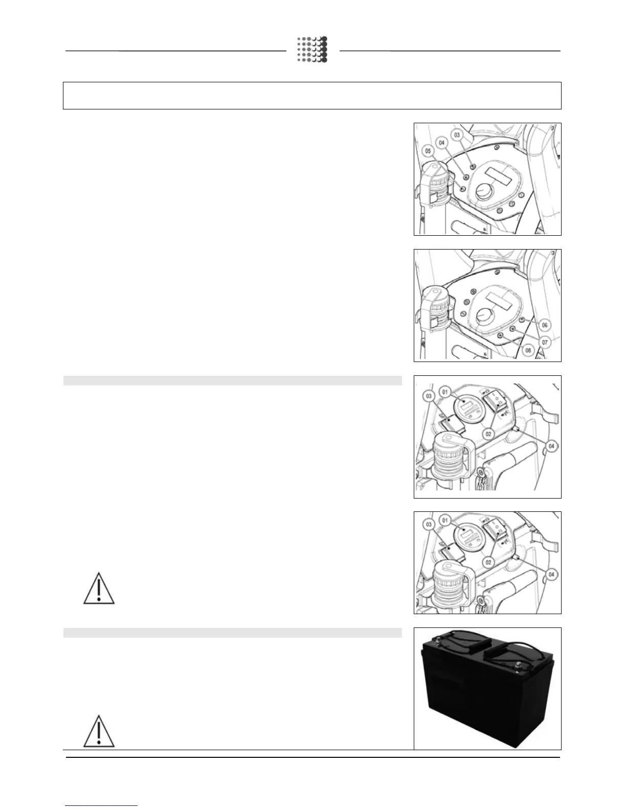
9. TYPE OF BATTERY
Power to th
e machine must be supplied by two sealed traction batteries with gas recombination or gel
technology. The batteries must meet the requirements laid out in the norms: CEI EN 60254
-5) + CEI EN 60254-2:2008-06 (CEI 21-7).
ance, the use of two 12V 77Ah/C5 batteries is recommended (size: 330 mm x 169 mm x H233mm
each with a weight of 27 kg), or two 12V 75Ah/C5 batteries (size: 259 mm x 169 mm x H2227mm each with a
weight of 25 kg).
WARNING: If batteries with weights or dimensions differing from those advised above
are used, the machine performance could vary considerably.
 Loading...