EasyManua.ls Logo

FineTek EPD30 - Din Pn40 & Pn16 & Pn10

FineTek EPD30
77 pages
Print Icon
To Next Page IconTo Next Page
To Previous Page IconTo Previous Page
Loading...
13
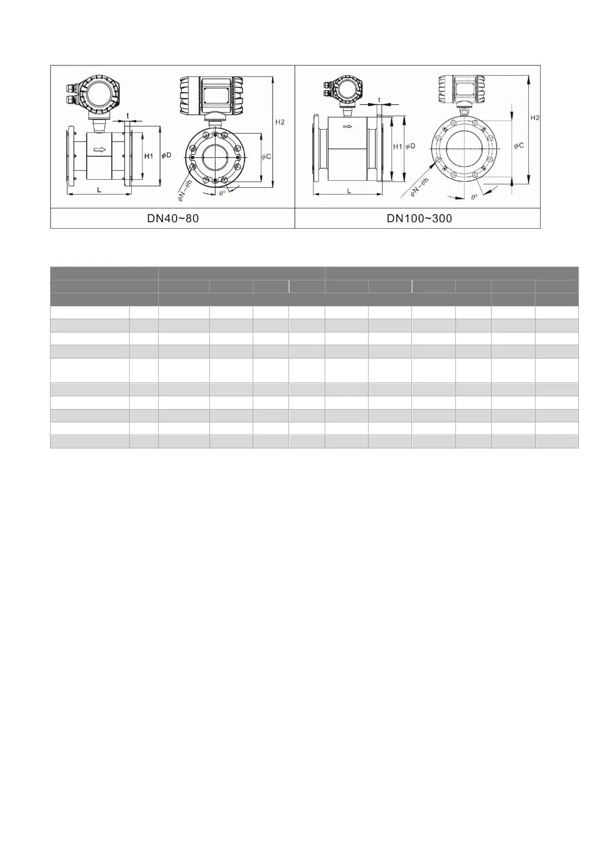
10.3 DIN PN40 & PN16 & PN10
Connection
specification
DIN PN40
DIN PN16
Nominal diameter(mm)
40
50
65
80
65
80
100
125
150
200
Lining material
PTFE
Length
L
200
200
200
200
200
200
250
250
300
350
External
diameter
ϕD
150
165
185
200
185
200
220
250
285
340
PCD
ϕC
110
125
145
160
145
160
180
210
240
295
Flange
thickness
t
18
20
22
24
18
20
20
22
22
24
Inclined angle of
screw hole
θ°
45
45
22.5
22.5
45
22.5
22.5
22.5
22.5
15.0
Diameter of
screw hole
θh
18
18
18
18
18
18
18
18
22
22
Quantity of
screw holes
N
4
4
8
8
4
8
8
8
8
12
Height of sensor
casing
H1
125
125
145
145
145
145
195
195
265
305
Total height
H2
320
327
347
355
347
355
390
405
470
510
Weight (kg)
-
7.08
7.72
8.98
12.25
8.58
11.65
15.62
20.96
28.23
39.97
Remarks: For DN40~DN80, the lining protective ring is 2mm, so the total length of the flow meter shall be
increased by L+4mm. For DN100~DN300, the lining protective ring is 0.5mm, so the total length of the flow
meter shall be increased by L+1mm; total length (L) tolerance is ±3mm, total height (H2) tolerance is ±5mm

Table of Contents