17
11.6 Notes for Installation on the Pipe
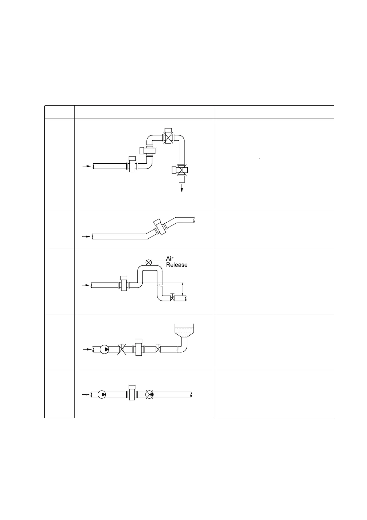
When installing the flow meter, one must follow the installation diagrams as shown
below. This will ensure the flow meter can guarantee the pipe is always filled with the
liquid: (The figures below are only typical cases, which don’t include all feasible
installation methods. The user may judge the installation position based on the actual
condition.)
installed at the pump outlet
rather than the inlet.
It should be installed at the
lower point and the vertically
upward point of the
horizontal pipe.
Don’t install it at the highest
point and the vertically
downward point of the pipe.
It should be installed at
the rising point of the
pipe.
If the pipe gap exceeds 5m,
the air release valve should
be installed at the
downstream of the sensor.
The downstream of the
sensor should have some
back pressure.
The control valve and cut
valve should be installed at
the downstream of the
sensor rather than the
upstream.
 Loading...