411UD Document #50759 Rev. E 12/09/2008 P/N 50759:E 9
Specifications
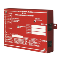
• Individual LEDs for:
Communication Fail (visible with cover on)
DACT Trouble (visible with cover on)
Channel Active (visible with cover on)
Primary Phone Line (PH1) active
Secondary Phone Line (PH2) active
Modem Active
• Piezo sounder
• Local piezo silence switch which silences onboard piezo sounder (accessible without removing cover)
• Real time clock
• Extensive transient protection
• One Form-C relay, fully programmable to activate for the following conditions:
fire alarm
host control panel trouble
fire supervisory
total communication failure
AC loss
DACT trouble (factory default for relay)
• PK-411 Remote Upload/Download Kit
• Industry-first, UL recognized 'dialer runaway' feature'
• Trouble Resound - if a trouble is silenced and the cause of the trouble is not cleared, the panel will resound
the trouble buzzer every midnight, until the trouble is cleared.
1.2 Specifications
Operating Power
The 411UD may be powered from UL listed control panels that output nonresettable and power-limited 12 or 24
VDC power. The configuration of Jumper J4 determines whether 12 VDC power is to be supplied directly to the
411UD circuit board or 24 VDC power is to be supplied and then internally regulated down internally to 12 VDC.
DC Power - TB1 Terminals 4(+) and 5(-), Terminal 6 is Earth Ground
• J4 Jumper removed - Filtered, nonresettable and power-limited 24 VDC (nominal) power must be supplied at
TB1 Terminals 4(+) and 5(-). Operating voltage provided must be within 21.3 to 24.0 VDC (UL tested range:
-15%, +10%). Current requirements are 100 mA in standby and 170 mA
1
while communicating.
• J4 Jumper installed - Filtered, nonresettable and power-limited 12 VDC (nominal) power must be supplied at
TB1 Terminals 4(+) and 5(-). Operating voltage provided must be within 11.2 to 12.4 VDC (UL tested range:
-15%, +10%). Current requirements are 100 mA in standby and 170 mA
1
while communicating.
1. A maximum of 300 mA is possible with all input channels shorted, the 411UD communicating, the Programmer connected and
Lamp Test active.