EQUIPMENT: FIRECLASS Prescient III WRITTEN BY: RKP
PUBLICATION: OMFCPRES3IN CHECKED BY: AP
ISSUE No. & DATE: 0 02/02/12
PAGE 39 of 43
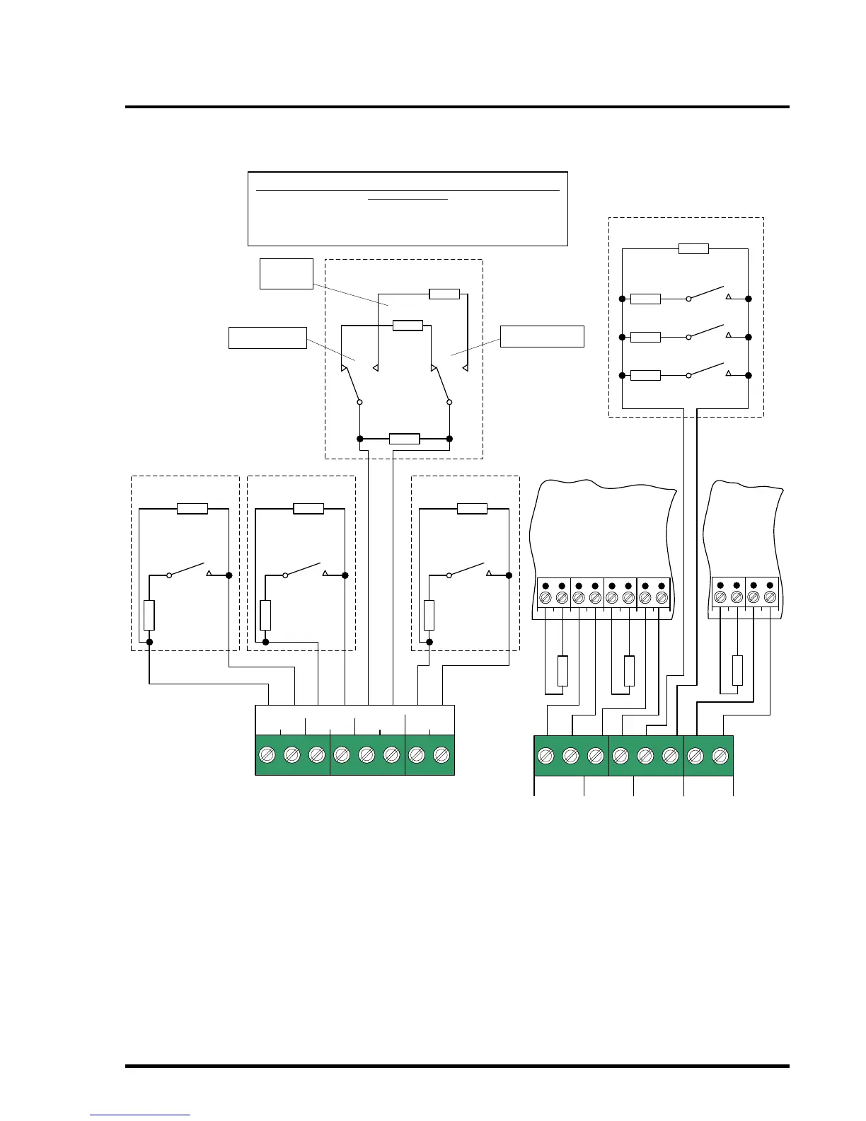
12.3 Monitored Inputs Connection Diagram
GAS
REL.
GAS
LOW
ISO.
VALVE
GAS
TRAPPED
HOLD ABORT
REMOTE
CTRLS
AUTO/
MANUAL
Isolation Valve is monitored for open circuit, short circuit, abnormal, fully open
& fully closed states.
Isolation Valve must be fitted with two SPDT limit switches; SW1 operates when valve
is fully open, SW2 when valve is fully closed.
Local terminal box may be required to accommodate monitoring resistors.
680R ¼ W
Normally
Open
Pressure
Switch
10K ¼ W
EOL
680R ¼ W
Normally Open or
Normally Closed
Low Pressure
Switch
10K ¼ W
EOL
2K2 ¼ W
Valve Open
680R ¼ W
Valve Closed
10K ¼ W
EOL
SW1
SW2
1 12
2
680R ¼ W
Normally
Open Gas
Trapped
Pressure
Switch
10K ¼ W
EOL
Normal
(Valve Open)
State
AUTO/MAN IN+
AUTO/MAN IN-
AUTO/MAN OUT+
AUTO/MAN OUT-
ABORT IN+
ABORT IN-
ABORT OUT+
ABORT OUT-
HOLD IN+
HOLD IN-
HOLD OUT+
HOLD OUT-
Connections to SLU
10K ¼ W EOL
10K ¼ W EOL
10K ¼ W EOL
Connections
to SLU
560R ¼ W
RESET
1K8 ¼ W
SILENCE
ALARMS
4K7 ¼ W
SOUND
ALARMS
10K ¼ W EOL
Panel Terminals
1 - Valve Fully Open
2 - Valve Not Open
1 - Valve Not Closed
2 - Valve Fully Closed