Long Range Radio Connections
Connect the data in/data out terminals and voltage
input terminals of the Long Range Radio to the
control's keypad connection points.
Set the radio’s address to “03” following the
instructions provided with the radio.
Notes
•
Use compatible Long Range Radios (e.g.,
7720PLUS, 7820, 7835C, or 7845C).
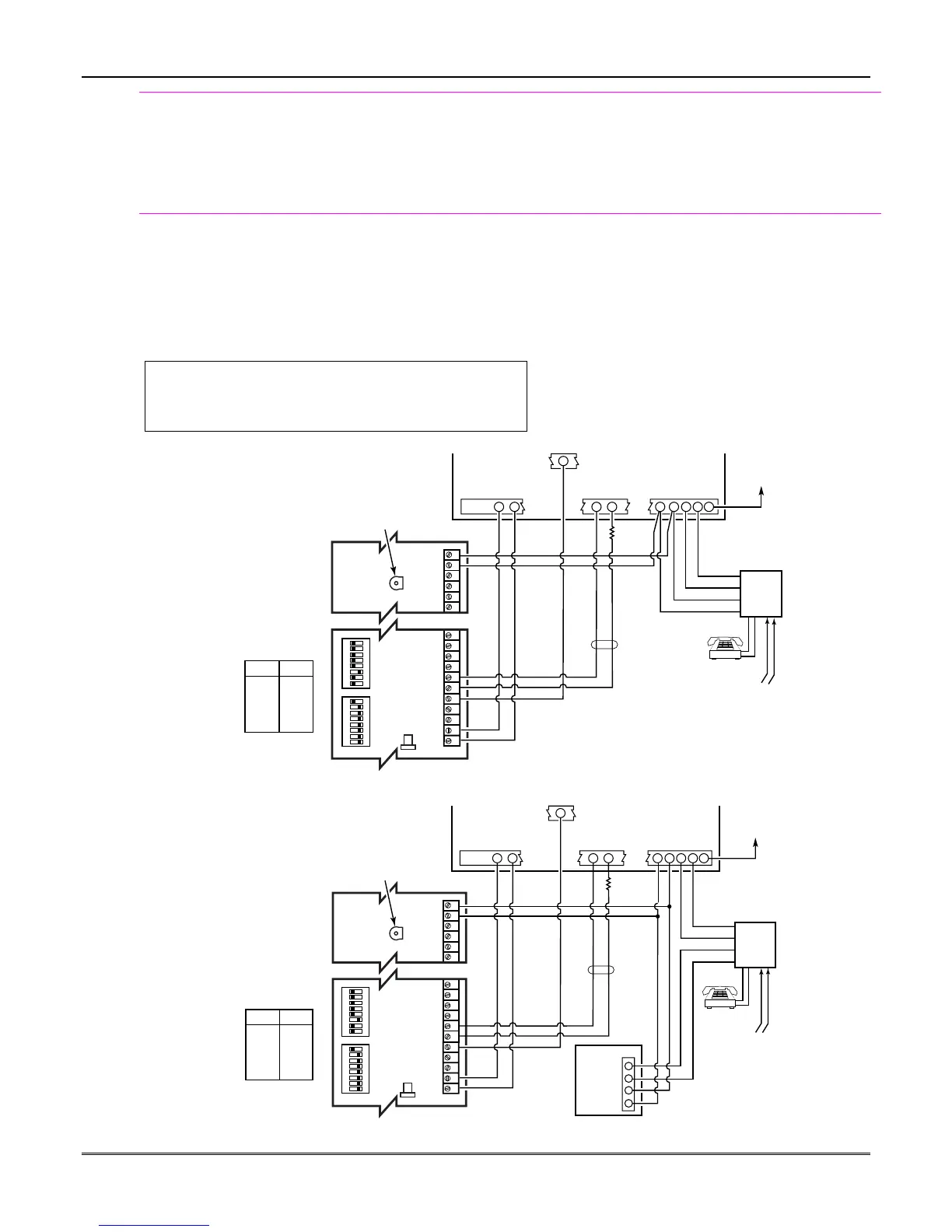
Audio Alarm Verification Connections
(AAV, “listen-in”)
Refer to the connection diagrams below. One diagram
shows connections when a FA4285/FA4286 Phone
Module is used, the other shows connections when
the FA4285/FA4286 is not used.
Connections use one of the on-board triggers.
U
L
UL installations using the AAV feature must use the
ADEMCO UVCM module (part of the ADEMCO UVS
system).
Suggested Module: ADEMCO UVS (shown) or Eagle 1250
Notes
•
Set field *91 for AAV and program the
appropriate output (output 17 or 18) using *80
Menu mode (select zone type “60”).
•
For voice session monitoring, connect an EOLR
zone to UVCM module terminals 6 & 7, and
program the zone as zone type 81 (*56 Menu
mode).
E.g., Using output 18 for the trigger, program an
output function in *80 Menu mode as: ZT = 60,
P = 0, Action = 1, Device = 18
ON ON
12345678 1 2345678
1234567891011
29 30 31 32 33 34
NOTE:
REFER TO UVCM MODULE
INSTRUCTIONS FOR
CONNECTIONS TO AUDIO
SPEAKERS AND MICROPHONE.
UVCM
MODULE
ZONE
TERMINALS
EARTH
GROUND
RED (R)
GREEN (T)
GREY (R)
BROWN (T)
TRIGGER
CONNECTOR
OUTPUT 18
EOL
RING
TIP
OPTIONAL
MONITORING ZONE
CONNECTION
(USE ZONE TYPE 81)
FALLING VOICE TRIG
GND
+12VDC IN
SWITCH
BANK 2
SWITCH
BANK 1
SWITCH BANK 2
SWITCH BANK 1
AUXILIARY
AUDIO LEVEL
ADJUSTMENT
TRIM POT
aav_uvcm-003-V0
CONTROL
INCOMING
PHONE LINE
TO
PREMISES
HANDSET
5
1 = ON
2 = ON
3 = OFF
4 = ON
5 = ON
6 = ON
7 = ON
8 = ON
1 = OFF
2 = OFF
3 = OFF
4 = OFF
5 = OFF
6 = OFF
7 = OFF
8 = ON
23
24
25
+12VDC
GND
4
5
21
22
RJ31X
Figure 15. Connection of AAV Unit When Not Using a FA4285/FA4286 Phone Module
1234567891011
29 30 31 32 33 34
NOTE:
REFER TO UVCM MODULE
INSTRUCTIONS FOR
CONNECTIONS TO AUDIO
SPEAKERS AND MICROPHONE.
UVCM
MODULE
CONTROL
EARTH
GROUND
RED (R)
GREEN (T)
GREY (R)
BROWN (T)
TRIGGER
CONNECTOR
OUTPUT 18
FA4285/FA4286
RING
TIP
FALLING VOICE TRIG
GND
+12VDC IN
SWITCH
BANK 2
SWITCH
BANK 1
SWITCH BANK 2
SWITCH BANK 1
AUXILIARY
AUDIO LEVEL
ADJUSTMENT
TRIM POT
10-aav_uvcm-001-V0
ZONE
TERMINALS
OPTIONAL
MONITORING
ZONE
CONNECTION
(USE ZONE
TYPE 81)
23 24
25
22
21
4
5
INCOMING
PHONE LINE
TO
PREMISES
HANDSET
RJ31X
2
3
4
1
5
1 = ON
2 = ON
3 = OFF
4 = ON
5 = ON
6 = ON
7 = ON
8 = ON
1 = OFF
2 = OFF
3 = OFF
4 = OFF
5 = OFF
6 = OFF
7 = OFF
8 = ON
ON ON
12345678 12345678
RING
TIP
+12VDC
GND
EOL
Figure 16. Connection of AAV Unit When Using a FA4285 or FA4286 Phone Module
Mounting and Wiring the Control
2-13