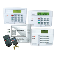
Keypads
Keypads are identified by predefined addresses (starting at address 16) as follows:
Address Keypad Program Field
16 keypad 1
•
always enabled for partition 1, all sounds enabled.
NOTE: First keypad is address 16.
17 keypad 2
•
data field *190
18 keypad 3
•
data field *191
19 keypad 4
•
data field *192
20 keypad 5
•
data field *193
21 keypad 6
•
data field *194
22 keypad 7
•
data field *195
23 keypad 8
•
data field *196
To enable keypads:
1. Set desired address at keypad (refer to keypad’s instructions for setting the address).
2. Use data field program mode to enable keypad addresses, assign a partition, enable sound options
in fields *190-*196 as shown in the table above.
3. If desired, use data field *198 to turn on the display of the partition number.
4. Set the following keypad-related data fields as required by the installation:
*21 Quick Arm Enable; *23 Forced Bypass, *84 Auto STAY Arm
5. If using AUI, enable each unit in field *189 and set AUI 1 to address 1, AUI 2 to address 2.
Wireless Receiver, Transmitters, and Wireless Keys (keyfobs)
Receiver:
Set the receiver’s address to “00” using its DIP switches, then set the following options:
*22 RF Jam Option
†
*24 RF House ID Code (if using wireless keypads) for each partition
*67 Transmitter Low Battery Report Code
†
*75 Transmitter Low battery restore report code
†
Transmitters:
Use *56 or *58 Zone Programming Menu modes to program zone information and
enroll transmitters (FA168CPS: zones 9-48, buttons 49-64; FA148CP: zones 9-34, buttons 49-56).
Wireless Keys:
Use Wireless Key Programming Templates section of the *58 Zone Programming
Menu mode to program zone information and enroll each button of the wireless keys used. Once a
wireless key is enrolled, it must be assigned to a user before it becomes active. See Adding/Deleting
Security Codes section for procedure.
Pager Programming
The system can send various reports to several pagers (FA168CPS = up to 4; FA148CP = up to 2).
1. Enter the appropriate information in the following data fields:
*160, *163, *166, *169 Pager Phone Numbers (for pagers 1-4
†
respectively)
*161, *164, *167, *170 Pager Prefix Characters (for pagers 1-4
†
respectively)
*162, *165, *168, *171 Pager Reporting Options by Partition
†
(for pagers 1-4 respectively)
2. Enable Pager Delay, if desired, in field *172 (delays alarm reporting for ALL pagers).
3. Make sure appropriate user open/close pager reports are enabled (see Security Codes, Assigning
attributes in Section 12. System Operation). Users that perform actions in partition 1 will, if
enabled, attempt to report to all pagers enabled for open/close reporting in partition 1. Users that
perform actions in partition 2 will, if enabled, attempt to report to all pagers enabled for
open/close reporting in partition 2.
4. If using latchkey pager report, define the latchkey report schedule using Scheduling mode (master
code + [#] [6] [4] select event type “03”). System must be armed for the Latchkey report to be sent.
5. If using a function key to manually send a message to a pager, see Function Keys on the next page.
6. If reporting zone alarms and troubles to a pager, use *81 Zone List menu mode to assign the zones
associated with each pager (zone lists 9-12
†
).
† FA168CPS supports four pagers and partitioning; FA148CP supports two pagers and zone lists 9
and 10 only.
†
These fields must be enabled for Residential
Fire, UL Residential Burglar Alarm, and UL
Commercial Bur
lar Alarm installations.
Installation Instructions
3-2