Quick Start Guide
D103556X012
DVC6200 Digital Valve Controllers
January 2017
36
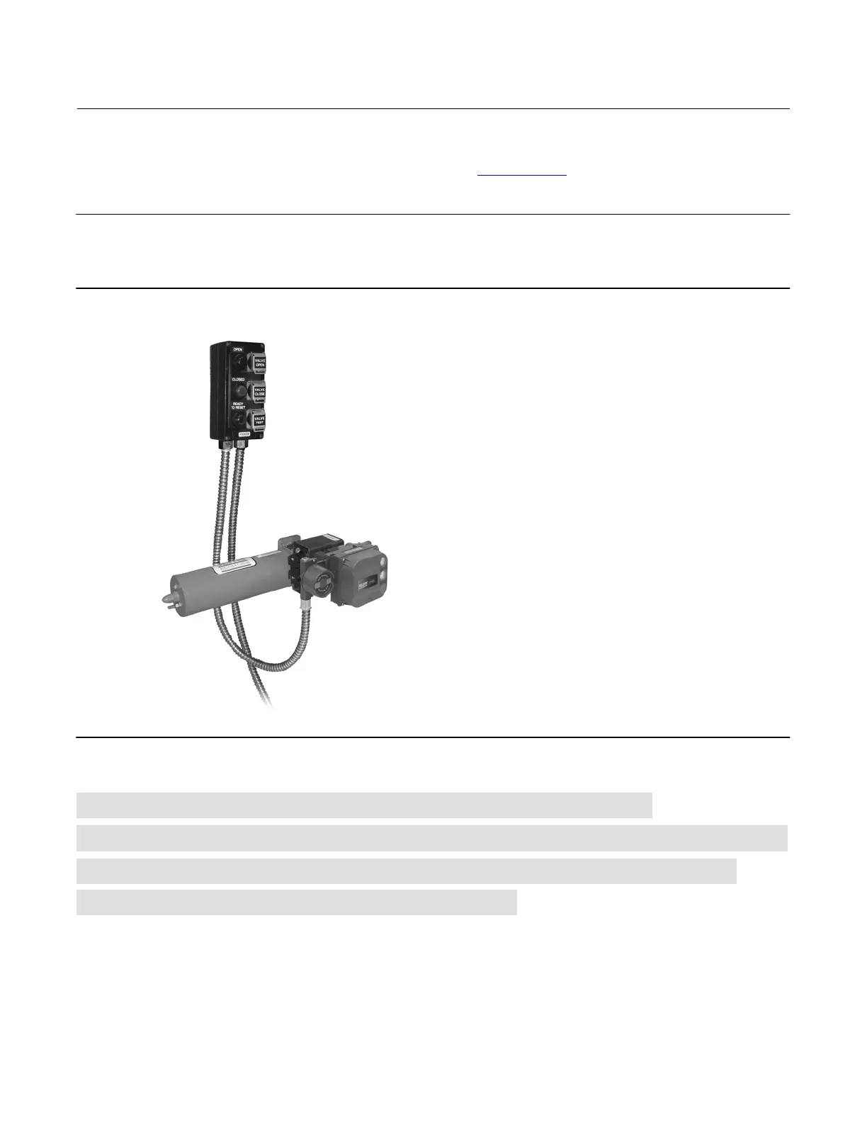
An optional local control panel (LCP100), shown in figure 29, can be installed to provide manual operation of the
DVC6200 SIS instrument. Refer to the LCP100 instruction manual (D103272X012
) for further information.
Note
If the LCP100 is connected to a DVC6200 SIS in a zone 1 explosion-proof “d” environment, there must be a conduit seal installed
between the DVC6200 SIS and the LCP100 in order to maintain the explosion-proof integrity of the DVC6200 SIS.
Figure 29. LCP100 Connected to a DVC6200 SIS Instrument
X0248
For de-energize to trip DVC6200 SIS, no solenoid valve, proceed to page 38
For de-energize to trip DVC6200 SIS and de-energize to trip solenoid valve, proceed to page 40
For DVC6200 SIS for PST only and de-energize to trip solenoid valve, proceed to page 42
For solenoid valve health monitoring, proceed to page 43
 Loading...


