GPS antenna
Radio antenna
23
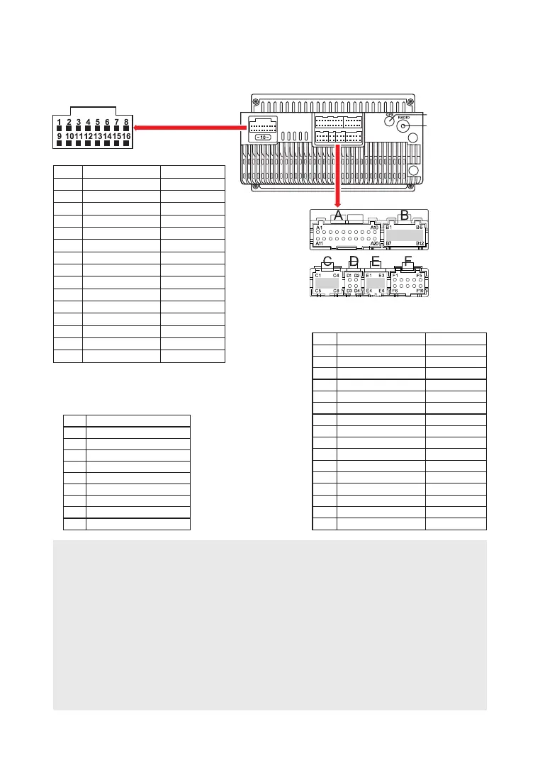
D I A G R A M C I R C U I T
Socket D - USB
1
2
3
4
5
6
7
8
9
10
11
12
13
14
15
16
GND
АСС
Back car control
Steering wheel 1
FR -
FR +
FL -
FL +
+12V
ILL
Steering wheel 2
Antenna
RL -
RL +
RR +
RR -
Black
Red
Pink
Green
Grey/Black
Grey
White/Black
White
Yellow
Orange
Grey
Blue
Green/Black
Green
Purple
Purple/Black
Socket F
F1
F2
F3
F4
F5
F6
F7
F8
F9
F10
Empty
Empty
Empty
Empty
Empty
BT antenna
GND
Back side camera
Empty
Wi-Fi antenna
Socket А
A1
A2
A3
A4
A8
A9
A10
A11
A12
A13
A14
A15
A16
A17
A18
A19
A20
Black
Red
White
Yellow
Black
Black
White
Red
Black
Black
Black
White
Yellow
Red
Transparent
Amplifier control В+
AUX Right speaker
AUX Le speaker
Empty
Empty
CVBS-in-2
MIC -
GND
Front le OUTPUT
Front right OUTPUT
GND
GND
GND
Video OUT
Subwoofer OUT
CVBS-in-1
MIC +
ATTENTION!
Incorrect connection of the receiver may damage it and void the right to warranty service. The
device uses power amplifiers connected in a bridge circuit. When connecting the speakers, do
not short-circuit the wires to the car body, to the + 12V power wire or to each other.
The red wire of the unit must be connected to the ignition circuit to avoid discharge of the
vehicle battery during prolonged parking.
The yellow wire of the device must be connected to a constant voltage wire + 12V, even with the
ignition off. If you have not found such a wire, then connect to the positive terminal of the
battery after the fuse box.
The black wire of the device must be connected to the car body. If you not find a suitable bolt or
screw, contact your nearest dealer for assistance Your car. To ensure good grounding, remove
paint and dirt from those areas of the surface with which the wire is in contact.
If the device is reset after turning off the ignition, swap connecting yellow and red wires