Supplement to User Manual - ENGLISH Modbus Server
SU_ModbusV2-8, 2015-03-02 83
B.2 Input of the CRT Entries
Max. 200 user-defined register addresses can be entered. If the standard register addresses are to remain valid besides
the user-defined register addresses, they also have to be entered.
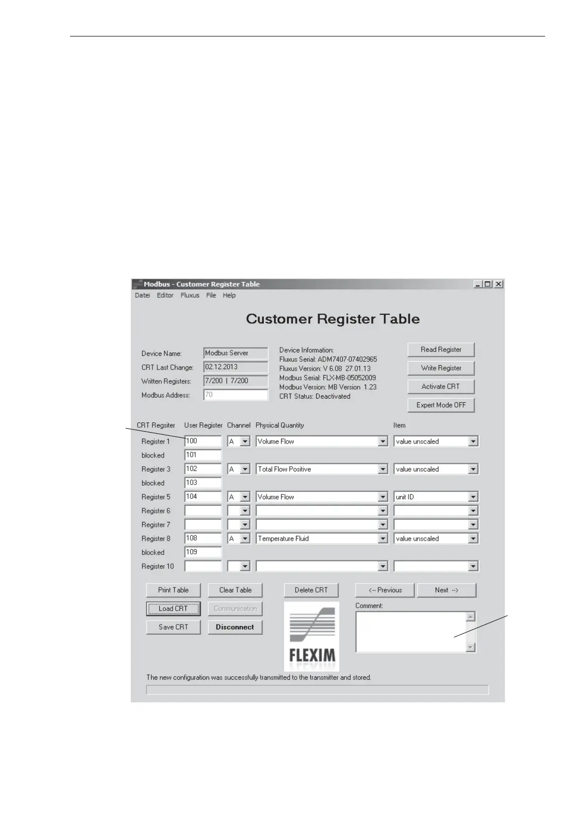
• Enter the user-defined register addresses (see Fig. B.4).
A measuring channel, a physical quantity and a parameter are assigned to every user-defined register address.
• Click the arrow keys.
• In the drop-down lists, select the measuring channel, the physical quantity and the parameter.
If the physical quantity is a channel-independent diagnostic value, "-" has to be selected as the measuring channel.
If more than one word is necessary for the mapping of the physical quantity, additional lines will be inserted. The user-de-
fined register addresses are completed automatically. The word order Little-Endian (hi word, lo word) is used.
• Click the button Next if more than 10 user-defined register addresses are to be entered in the table.
• Click the button Previous if the previous 10 user-defined register addresses are to be displayed again.
A comment can be entered. It can be stored in a configuration file and printed out (see text field in Fig. B.4 and section
"Storing and Transmission").
Fig. B.4: Input of user-defined register addresses
input field
(user-
defined
register
addresses)
text field