F R O N T C O N S O L E C H A P T E R 3
Without RX2 installed or with RX2 installed but Off:
o VFO B displays in red the transmit frequency when operating split (SPLT button
active).
o VFO B displays in yellow the second receive channel's frequency when activating the
multi receive function (MultiRX button active). Otherwise, it can be viewed as a storage
container to copy VFO data to and from VFO A (see the VFO Controls section on page
71).
With RX2 installed and On, VFO B tunes RX2 exclusively. In this case the RX1 split or multi RX
frequencies are displayed in the lower section of VFO A (see above).
o The red TX indicator identifies the transmit frequency. Clicking on the TX indicator of
VFO A or VFO B will change the transmit frequency to either RX1 (VFO A) or RX2
(VFO B).
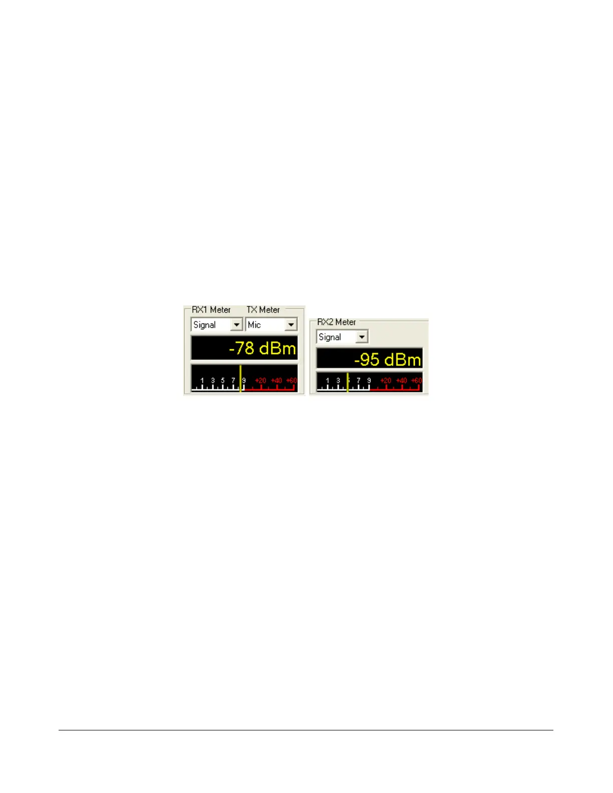
(4 and 4b) Multimeters
Figure 37: Primary (left) and RX2 (right) Multimeters
The multimeter displays both digitally and graphically various RX and TX signal parameters as
determined by the selection from the (two) drop down boxes at the top.
The text display below the meter selections shows the digital data for either the receiver or the
transmitter (Signal strength in Figure 37 above). The lower display at the bottom of this section shows
the data graphically as an edge meter. Alternatively a bar graph display can be selected (see the
description of the Setup Form - Appearance Tab, Meter Sub-Tab on page 121).
RX1 and RX2 Meters
Signal (Signal Level): Calculates the true RMS power in dBm of the current signal within the
passband, as measured at the selected FLEX-5000 antenna port.
Sig Avg (Signal Average): Calculates the true RMS power in dBm of a time-averaged signal
within the passband, as measured at the selected FLEX-5000 antenna port.
ADC L (Analog To Digital Left): Calculates the level in dBFS (decibel full scale) of the Left
input from the internal I/Q ADC.
ADC R (Analog To Digital Right): Calculates the level in dBFS (decibel full scale) of the Right
input from the internal I/Q ADC.
53 2003-2008 FlexRadio Systems