F R O N T C O N S O L E C H A P T E R 3
Scope
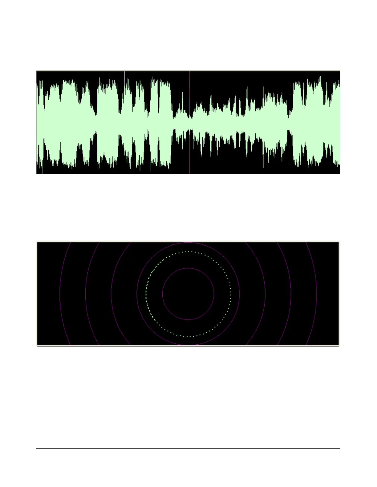
Figure 51: Scope Display
The Scope Display shows the received or transmitted audio signal in the time domain. Shown is an SSB
signal. The Scope Display is particularly useful when transmitting to monitor your audio waveform, e.g.
to see the effects of DX (page 59) or equalization (page 139). The time base can be adjusted on the
Setup Form- Display Tab (see page 98).
Phase
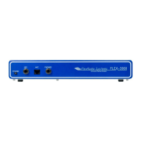
Figure 52: Phase Display
The Phase Display maps the filtered I and Q (Left and Right) channels to the X and Y coordinate planes.
This is useful for making sure the two channels are 90 degrees out of phase as they should be. There is
also a Phase2 Display that maps the unfiltered data directly from the ADC. When a continuous carrier
signal is received, the unfiltered data in the Phase2 Display should produce as near to a perfect circle
as possible. If the circle distorts into an oval or a straight line, the input phase is off balance which
would indicate a connection or hardware problem.
[The rest of this page has been left blank intentionally]
67 2003-2008 FlexRadio Systems