1
Getting Started
1. GETTING STARTED
The system comes with the following
components:
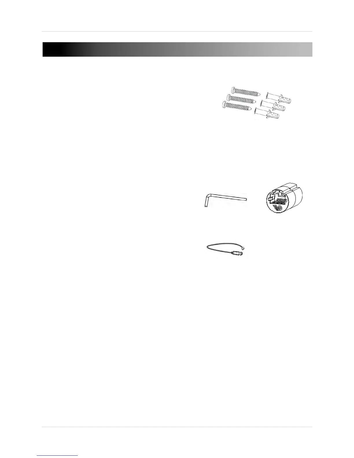
Allen Key
RJ45 Coupler
BNC Test Cable
Mounting Screw Kit:
• 3x mounting screws
(PA4 30mm)
• 3x drywall anchors
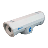
• 1 x Camera
• 1 x Mounting Screw Kit
• 1 x Allen Key
• 1 x RJ45 Coupler
• 1 x BNC Test Cable
• 1 x Mounting Template
• 1 x Quick Start Guide
• 1 x Software/Documentation CD
1.1 Default Camera Username, Password, and Ports
Username: admin
Password: admin
Ports: 80 (HTTP), 30001 (Control/Streaming), 8080 (RTMP),
554 (RTS
P)
IP Address: DHCP Enable
d by Default (Router will automatically assign IP
address)
NOTE: Onc
e you have completed the basic setup of the camera, it is
r
ecommended to configure a static IP address. This will prevent the camera
IP address changing in the event of a power failure. For details, see “6.7.1
Local Network” on page 27.