8
Camera Installation
3. CAMERA INSTALLATION
All Installation Methods
NOTE: Acceptable mounting surfaces for wall/
ceiling mounts are as follows:
• Concrete wall/ceiling.
• Plasterboard wall/ceiling.
• Solid board wall/ceiling.
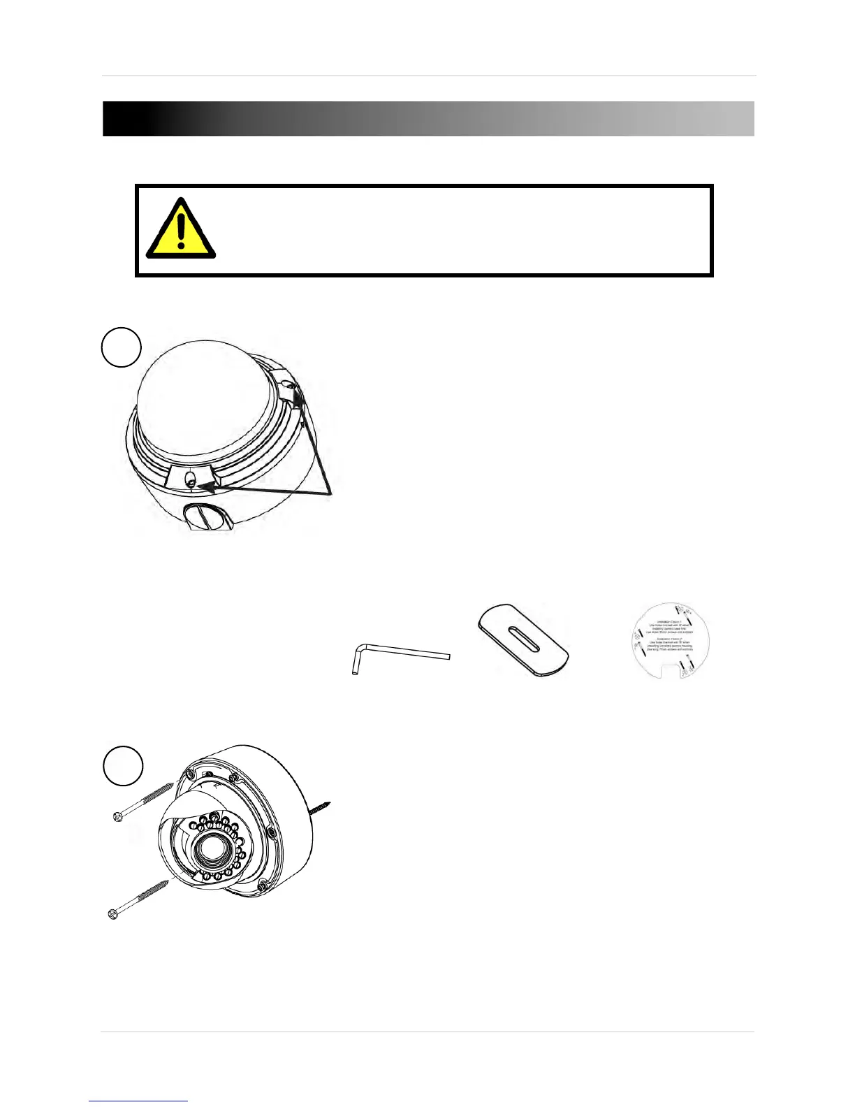
1.Loosen the thre
e tamper screws using the
provided allen key. Lift the dome cover.
NOTE: If you plan to use conduit fitting, remove
c
onduit cap using the provided conduit key.
Allen Key
Conduit Key
Mounting Template
Method 1 - Direct Attach Install
2a. Use the included mounting te
mplate
(Installation Option 2) to mark and pre-drill
the required holes.
Remove 2 of the 3 base locking screws. Use
2pc of the 2.8” screws to mount the camera
dire
ctly to the mounting surface.
Remove the 3rd base locking screw and install
the 3rd 2.8” screw.
Go to step 4 to complete installation.
Make sure to follow the correct polarity if connecting
the camera to DC power. Polarity is marked on the
power connector.