9
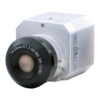
Camera Installation
Method 2 - Camera Base Install
2b. Use the included mounting te
mplate (Installation Option 1) to mark and
pre-drill the required holes.
2c.
Remove the camera
base by unscrewing the 3
base lo
cking screws, and
turn camera module
approx. 5 degrees
counterclockwise to detach
camera base from the
camera module.
2d. Ins
tall the base to the
c
orrect holes as indicated
on the mount template
using the 1.2” screws.
Go to step 3a to complete
ins
t
allation.
Method 3 - Junction Box
Install
2e. Attach provided fitting
plat
e to junction box (see “5.
Junction Box Installation
Types” on page 14).
2f. Remo
ve the camera
base by unscr
ewing the 3
base locking screws, and
turn the camera module
approx. 5 degrees
counterclockwise to detach
camera base from camera
module.
2g. Ins
tall the base to the
junction bo
x plate using the
base fitting screws.
Go to step 3a to complete
inst
allation.