3 – Getting Started
10 Oct 2010 427-0026-01-10, version 110
Step 5 Route the 22’ JCU cable from the cable splice connector to
the Joystick Control Unit mounting location and the 22’ video
cable from the video cable splice connector to the monitor.
See Figure 3-1 for a schematic representation of the cabling
connections.
Step 6 Securely attach the green ground wire to the vehicle ground
plane.
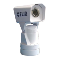
Figure 3-4: Securing the Camera
flat washer (4)
lock washer (4)
screw (4)
mounting
surface

 Loading...