INSTALLATION INSTRUCTIONS
18
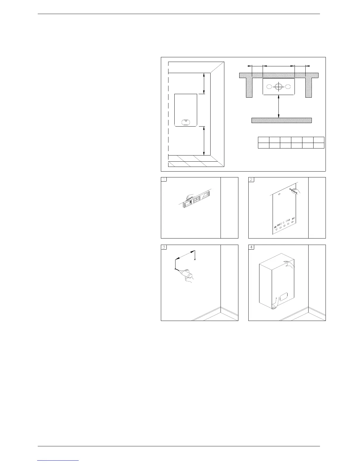
3.3 Installing the water heater
■ The appliance must be installed
exclusively on a flat vertical solid wall
capable of supporting its weight.
■ The water heater should be fitted within
the building unless otherwise protected
by a suitable enclosure i.e. garage or
outhouse. (the water heater may be fitted
inside a cupboard).
■ If the water heater is sited in an unheated
enclosure then it is recommended to
leave the power on to give frost
protection (frost protection is active even
with on/off switch in off position).
■ If a water heater is installed in a closed
water supply system, such as one having
a back flow preventer in the cold water
supply line, means shall be provided to
control thermal expansion. Contact the
water supplier or local plumbing inspector
on how to control this situation.
In order to allow access to the interior of the
water heater for maintenance purposes, it is
important that the necessary clearances
indicated in figure 1 are respected. To make
the installation easier, the water heater is
supplied with a template to enable the pipe
connections to be positioned prior to fixing
the appliance to the wall.
To install the water heater, proceed as
follows (see fig. 2):
a. Use a spirit level (of not less than 25 mm
long) to mark a horizontal line on the wall
where the water heater is to be fitted.
b. Position the top of the template along the
line drawn with the level, respecting the
distances indicated. Then mark the
centres of the positions of the two wall-
plugs or anchors. Finally, mark the
positions of the water and gas pipes.
c. Remove the template and install the
supplied bracket securely to the wall.
Once the water heater is securely
installed, connect the domestic hot and
cold water pipes, the gas supply pipe and
the central heating pipes using the fittings
supplied with the water heater.
d. Clearance to Combustibles-
Front –0 inches
Sides – 0 inches
Rear – 0 inches
Top – 0 inches from jacket cover
M o del
FLO W M A X - 120
1 2
BA
B
0 0
16
2 4
HLYX
Y
L
X
A
H
M IN IM U M D IS T A N C E S [IN C H E S ]
12
Fig. 1
Fig. 2