INSTALLATION INSTRUCTIONS
36
4.2 Filling the system
Check the properties of the water supply and install the
appropriate treatment devices if the mains water has a
hardness rating more than 14.5 gpg (250 mg/L) i
n
order
to prevent scaling and eventual damage to the D.H.W
heat exchanger.
Use only clean tap water to fill the system.
A pre-filtering system can be installed on the incoming
water supply to help reduce impurities and limestone.
This water heater must have adequate water flowing
through it whenever the burner is on. Failure to do this
will damage the unit and void the warranty.
Once the water pipes have been connected, close the gas feed
valve and fill the system as follows:
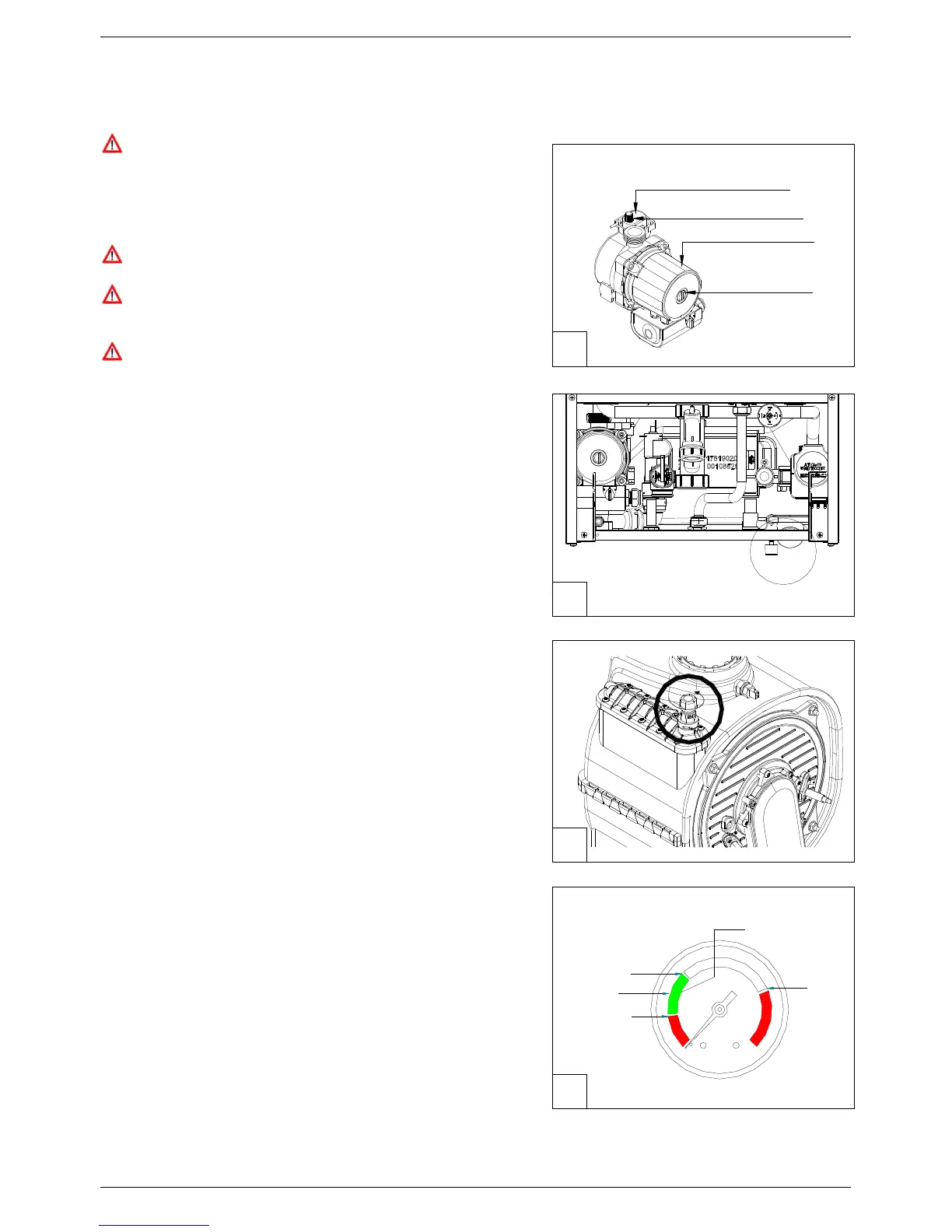
• Check that the circulation pump runs freely;
• Check that the plug of the air vent valve has been slackened
slightly to allow air to escape from the system (fig.1);
• Open the main domestic water supply valve;
• Open the filling tap R (fig. 2);
• Unscrew the plug on the pump to remove any trapped air,
check that the pump is free then re-tighten it when water
starts to flow out (fig.1);
• Before switching on the water heater, purge air
completely from the air vent valve positioned on the top
of the condensing exchanger (fig. 3);
• Open the air vents on the radiators and monitor the air
evacuation process. When water starts to flow out of the
radiators, close the air vents;
• Use the pressure gauge M (fig. 2), to check that the systems
pressure reaches the middle of the green area (equal to 1,2
bar, see fig. 4).
•
On completion, make sure that the filling tap R is
perfectly closed.
3
2
1
4
3 bar
1.5 bar
0.5 bar
1.2 bar
GREEN AREA
AIR VENT VALVE PLUG
PUMP PLUG
PUMP
AIR VENT VALVE
M
R