INSTALLATION INSTRUCTIONS
27
3.8.3 Remote control connection
Connect the power supply to the terminal board inside the control panel as follows:
a. Switch off the power supply at the main switch.
b. Remove the front case panel of the water heater.
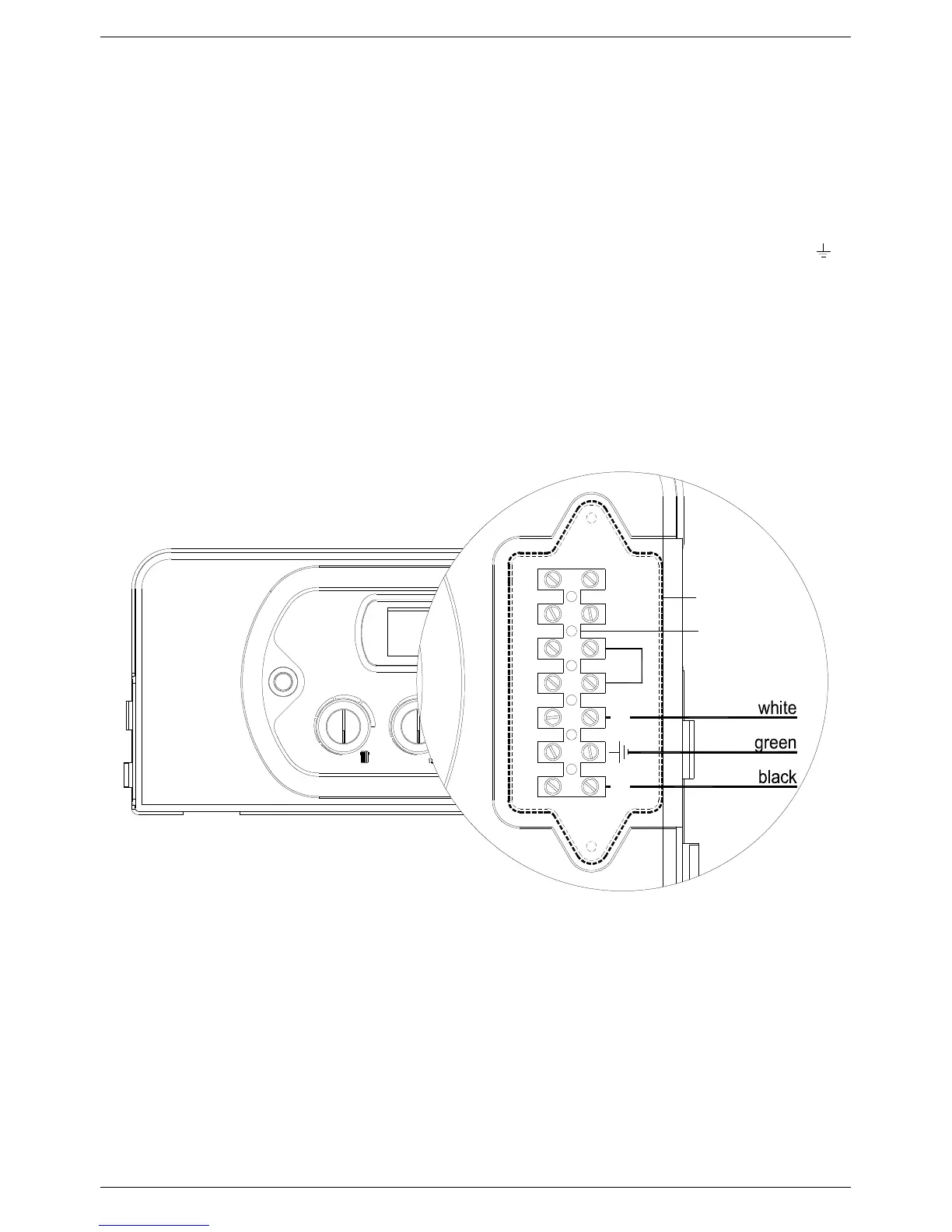
c. Slacken the screws and remove plate A (see fig. 1).
d. With the plate removed, connect the wires to the terminal board B as follows:
• Connect the ground wire (normally coloured green/yellow) to the terminal marked with the ground symbol “ “.
• Connect the neutral wire (normally coloured blue) to the terminal marked with the letter “N”.
• Connect the live wire (normally coloured brown) to the terminal marked with the letter “L”.
• Terminals identified by the letters: Ta ⇒ Room thermostat
Se ⇒ Outside temperature sensor
When the wires have been connected, place plate “A" back to position.
TaL N Ta Se Se
B
A
Fig. 1