MAINTENANCE INSTRUCTIONS
55
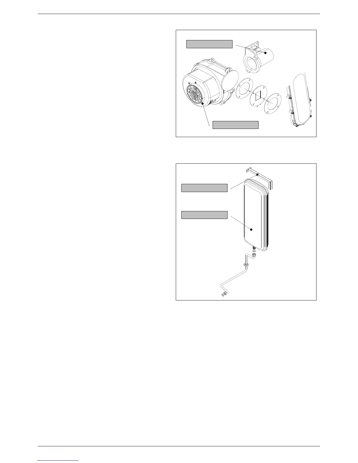
Electric fan
(see fig. 1)
• Remove and dismantle the entire burner unit (see
6.6.1 “Cleaning the burner unit”).
• Use an 8 mm wrench to unscrew the four nuts
securing the electric fan to the gas manifold and
then remove the electric fan, noting the positions of
the washer and diaphragm.
• Remove the air intake duct, unscrew the two fixing
screws from the venturi and remove the electric
fan, paying particular attention not to damage the
cork gasket.
• Replace the electric fan and re-assemble the
components following the above procedure in
reverse order.
• Switch on the electricity, water and gas supplies
and check the soundness of the joint by measuring
the CO
2
levels;
Expansion tank
(see fig. 2)
• Close the shut-off valves and drain the central
heating circuit of the water heater.
• Use a 19 mm wrench to unscrew the pipe
coupling to the vessel.
• Unscrew the fixing screws and remove the upper
mounting bracket. Remove the expansion vessel
from the front of the water heater.
• Replace the expansion vessel and re-assemble
the components following the above procedure in
reverse order.
• Switch on the electricity, water and gas supplies
and fill the system with water. Check for any leaks
from the joints and bleed off any air from the
circuit;
fixing bracket
expansion tank
Fig. 2
venturi
electric fan
Fig. 1