MAINTENANCE INSTRUCTIONS
64
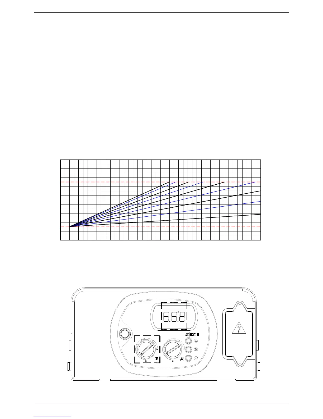
Regulating the Flow temperature in accordance with the outdoor temperature
The outdoor sensor has to be connected directly to circuit board SM 20021. The sensor can thus be managed in
one of two ways:
• In case of remote controller + outdoor temperature sensor installation, the climatic compensation curve is set by
the remote itself (see remote control installation and operating manual).
• In case of outdoor temperature sensor only installation, the climatic compensation curve is set using the central
heating control knob. As the knob (see fig. 2) is rotated, the numbers corresponding to the curve shown in figure
1 are displayed
The factors governing the correction are reported in figure 1.
The selection of the compensation curve is determined by the maximum delivery temperature Tm and the minimum
outdoor temperature Te.
N.B. The y-axis values of the delivery temperature Tm refer to standard 167-86°F appliances or 104-77°F floor-
mounted appliances. The type of appliance can be programmed using parameter 3 (see 5.1 “Parameter
programming”).
13
OUTDOOR SENSOR
DELIVERY TEMPERATURE CORRECTION AS A FUNCTION OF OUTSIDE
TEMPERATURE WITH RESPECT TO THE POSITION OF THE HEATING
TEMPERATURE CONTROL SET BY THE USER
TM-MAX/MIN = delivery temperature range selected
MIN
27 26 192425 23 2122 20 1618 17 15 14
Tm
Te = Outdoor temperature Tm = delivery temperature
-121012 11 89 7 56 4 23 1 -6-3-10 -2 -4 -5 -9-7 -8 -10 -11
8
9
7
6 5
0
Te (°C)
-15-13 -14
1
2
3
4
95
86
77
176MAX104
95
86
104
113
122
131
140
149
158
167
120 60 Hz
Fig. 1
Fig. 2