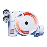
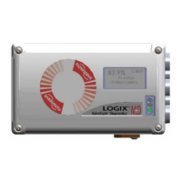
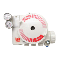
Logix
®
420 Digital Positioner FCD LGENIM0106-07-AQ – 10/15
42
INDEX
A
Air Action Switch · 15
Air Supply · 6
Auto Tune Switch · 16
C
Calibration · 16, 17, 21, 22, 23, 34, 36, 37
Characterization · 15, 16, 23
Command Source Reset · 18
Compliance Voltage · 12
Configuration Switch Settings · 15
D
DIP Switch Override · 20
Display Contrast · 20
E
Electrical Connections · 12
Event History · 21, 22
F
Factory Reset · 18, 26
FlowTop · 9
Friction · 16, 20, 36
H
Handheld Communicator · 27
HART · 4, 6, 20, 26, 27, 29
Hazardous Area Certifications · 7
I
Inner Loop · 5
Installation · 9
L
Language · 26
LCD Menu · 19
Limit Switch · 14
Local Control Of Valve Position · 18
Local User Interface · 15
M
Main Board · 30
Maintenance · 8, 29, 30
MaxFlo Rotary Valves · 10
Minimum Close Time · 23
Minimum Open Time · 23
Mounting · 9
O
Outer Loop · 5
P
Partial Stroke Test · 21, 22, 33
Performance · 6
Positioner Dimensions · 40
Pressure Control · 16, 20, 24
Q
Quick Calibration Switch · 16
Quick-Cal · 15
R
Repair · 30
S
Safety · 3
Shutoff · 25
Signal at Closed Switch · 15
Soft Limits · 25
Spare Parts · 3, 41
Specifications · 6
Status Code · 16, 32, 33
Status Icons · 20
Status Messages · 20
Stroke Calibration · 15, 16
Stroke Time ·23
 Loading...

