Logix
®
420 Digital Positioner FCD LGENIM0106-07-AQ – 10/15
6
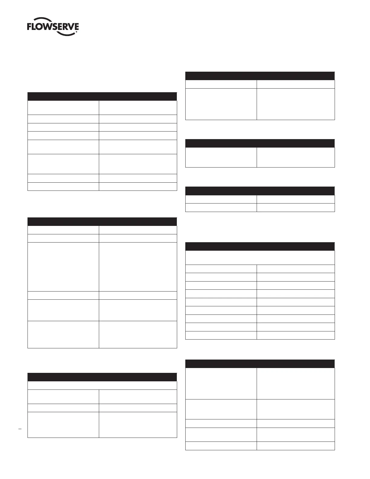
2 SPECIFICATIONS
2.1 Input Signal
Table 1: Input Signal
Power Supply
Two-wire, 4-20 mA
10.0 VDC terminal voltage
Input Signal Range 4 - 20 mA (HART)
Compliance Voltage 10.0 VDC @ 20 mA
Effective Resistance 500 Ω @ 20 mA Typical
Minimum Required
Operating Current
3.8 mA
Signal Interrupt Without Restart
Time (after powering positioner
for at least one minute)
80 ms
Maximum Shut-down Current 3.6 mA
Communications HART protocol
2.2 Air Supply
Table 2: Air Supply
Minimum Input Pressure 1.5 Bar (22 PSI)
Maximum Input Pressure Single Acting Relay – 6 Bar (87 PSI)
Air Supply Quality The air supply must be free from
moisture, oil and dust by conforming
to the ISA 7.0.01 standard. (A dew
point at least 18 degrees Fahrenheit
below ambient temperature, particle
size below five microns—one micron
recommended—and oil content not to
exceed one part per million).
Operating Humidity 0 - 100% non-condensing
Acceptable Supply Gasses Air, sweet natural gas, nitrogen and
CO2 are acceptable supply gasses.
Sour natural gas is not acceptable.
Air Consumption
0.069 Nm³/h @ 1.5 bar
(0.041 SCFM @ 22 PSI)
0.082 Nm³/h @ 4.1 bar
(0.050 SCFM @ 60 PSI)
2.3 Physical Specifications
Table 3: Physical Specifications
For dimensions, see section 15 POSITIONER DIMENSIONS.
Housing Material Cast, powder-painted aluminum
EN AC-AlSi12(Fe)
Soft Goods Fluorosilicone
Weight of Base Positioner
Without Accessories
With LCD and Glass Cover
2.70 kg (5.95 lb)
With Solid Cover
3.11 kg (6.85 lb)
2.4 Pneumatic Output
Table 4: Pneumatic Output
Output Pressure Range 0 to 100% of air supply pressure.
Output Air Capacity
Single Acting Relay –
9.06 Nm³/h @ 1.5 bar
(5.33 SCFM @ 22 PSI)
20.8 Nm³/h @ 4.1 bar
(12.2 SCFM @ 60 PSI)
2.5 Stroke Output
Table 5: Stroke Output
Feedback shaft Rotation
Min 15°, Max 90°
45° recommended for linear
applications.
2.6 Temperature
Table 6: Temperature
Operating Temperature Range* -52 to 85°C (-61.6 to 185°F)
Transport and Storage Range -52 to 85°C (-61.6 to 185°F)
*Reduced performance at low temperatures.
2.7 Positioner Performance Characteristics
Table 7: Performance Characteristics
Better than or equal to the following values on a 25 square inch Mark I
actuator per standard ISA 75.13.
Resolution ≤ 0.25%
Linearity +/-1.25%
Repeatability ≤ 0.25%
Hysteresis ≤ 1.0%
Deadband ≤ 0.3%
Sensitivity ≤ 0.25%
Stability ≤ 0.4%
Long term drift ≤ 0.5%
Supply Pressure Effect ≤ 0.2%
2.8 ValveSight DTM Software Specifications
Table 8: Pneumatic Output
Computer Minimum Pentium processor running
Windows 95, 98, NT, 2000, XP, 32 MB
total memory (64 MB recommended),
30 MB available hard disk space,
CD-ROM drive
Ports 1 minimum available with 8 maximum
possible. (Can also communicate via
serial, PCMCIA and USB connections)
HART Modem RS-232, PCMCIA card, or USB
HART Filter May be required in conjunction with
some DCS hardware.
HART MUX MTL 4840/ELCON 2700