Take careful notice of all safety and precautionary measures indicated in paragraph
4.4: Electrical Installation and review paragraph 4.4.3 and 4.4.4 before applying any
field or power supply wiring.
To prevent the disconnection of live circuits in hazardous area, always use the
supplied cable connectors with at least 5 poles to ensure proper strain relief.
4.6.1 OVERVIEW
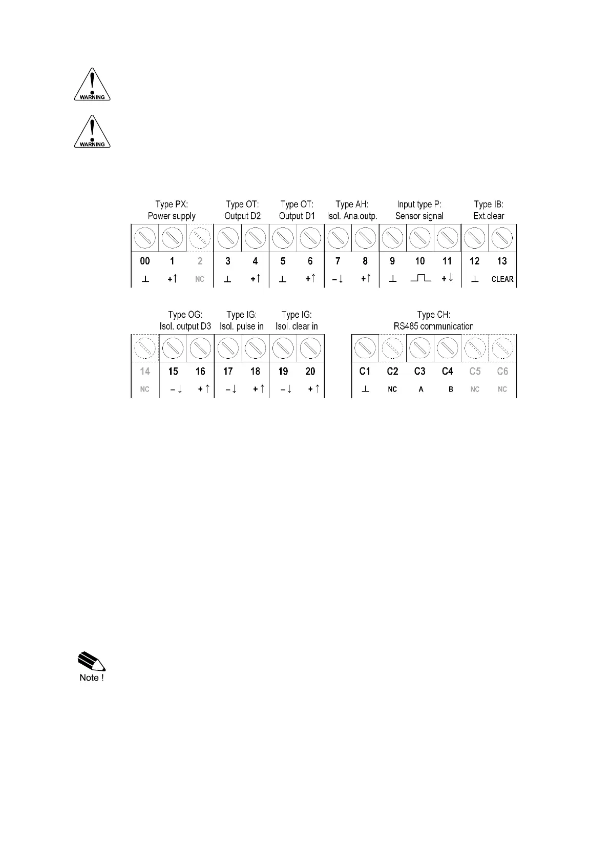
The following terminal connectors are available on the F103-P:
Fig. 24: Overview of terminal connectors - Standard configuration
4.6.2 TERMINAL 00-01: POWER SUPPLY – TYPE PX
Connect an external power supply of 6-30VDC to these terminals. The connected supply is used to
power the unit, the backlight and the sensor supply. When power is applied to these terminals,
discharge of the (optional) internal battery will be disabled.
Please read paragraph 4.4.4: Power supply wiring for specific requirements.
4.6.3 TERMINAL 03-04 AND 05-06: DIGITAL OUTPUTS D1 AND D2 – TYPE OT / TYPE OG
Digital output D1 always functions in retransmit mode where the frequency of the flowmeter signal
is retransmitted. This signal is often used when sinus / non-square wave input signals are present
(e.g. coil signals) that need to be transmitted as robust square wave forms.
Digital output D2 offers a scaled pulse output and its function is determined by the settings of
SETUP-menu 8: Pulse Output (see chapter 3).
If an isolated connection to a scaled pulse output is required, please see Terminal 15-16: Isolated
digital output D3 – Type OG.
Digital output D2 and digital output D3 are configured by the same settings of SETUP-
menu 8: Pulse output. Please make sure to program the settings in such a way that the
maximum output frequency is not exceeded (500Hz for D2 and 50Hz for D3).