Page 39
FW-F103-P-XN-M_v2002_03_EN.docx
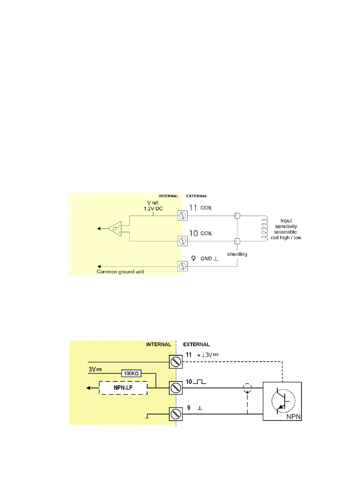
4.6.5 TERMINAL 09-11: FLOWMETER INPUT
Three basic types of flowmeter signals can be connected to the unit: pulse, active pulse or sine-
wave (coil). The screen of the signal wire must be connected to the common ground terminal 09
(unless earthed at the sensor itself).
The maximum input frequency is approximately 10 kHz (depending on the type of signal). The input
signal type has to be selected in SETUP-menu 5: Flowmeter (read chapter 3).
The following safety parameters are applicable to terminals 9, 10 and 11:
V
in-max
= 10 Vdc or peak
V
oc
= 5.1 Vdc
I
sc
= 1.9 mA
P
o
= 2.4 mW
C
a
= 1000 μF
L
a
= 3 H
To connect an active flowmeter signal, please see Terminal 17-18: Isolated pulse input – Type IG.
Sine-wave signal (Coil)
The F103-P is suitable for use with flowmeters which have a coil output signal.
Two sensitivity levels can be selected:
• COIL-LO: sensitivity from about 80mV
pp
;
• COIL-HI: sensitivity from about 20mV
pp
;
Fig. 27: Terminal connections - Coil signal input
Pulse-signal NPN / NPN-LP
The F103-P is suitable for use with flowmeters which have a NPN output signal. For reliable pulse
detection, the pulse amplitude has to go below 1.2V. Signal setting NPN-LP employs a low-pass
signal noise filter, which limits the maximum input frequency (read chapter 3).
Fig. 28: Terminal connections – NPN signal input