MegOhmMeter
Performance Test
7
Performance Test
WWarning
While performing the following procedures, there are potentially
dangerous voltages at the Meter output terminals when the
Meter is in the MΩ function.
The following performance tests will ensure that the meter is in proper operating
condition and meets the published accuracy specifications. If the Meter fails any of the
performance test steps, repair is needed.
To perform the tests you will need equipment meeting the minimum specification given
in Table 2.
Display Test
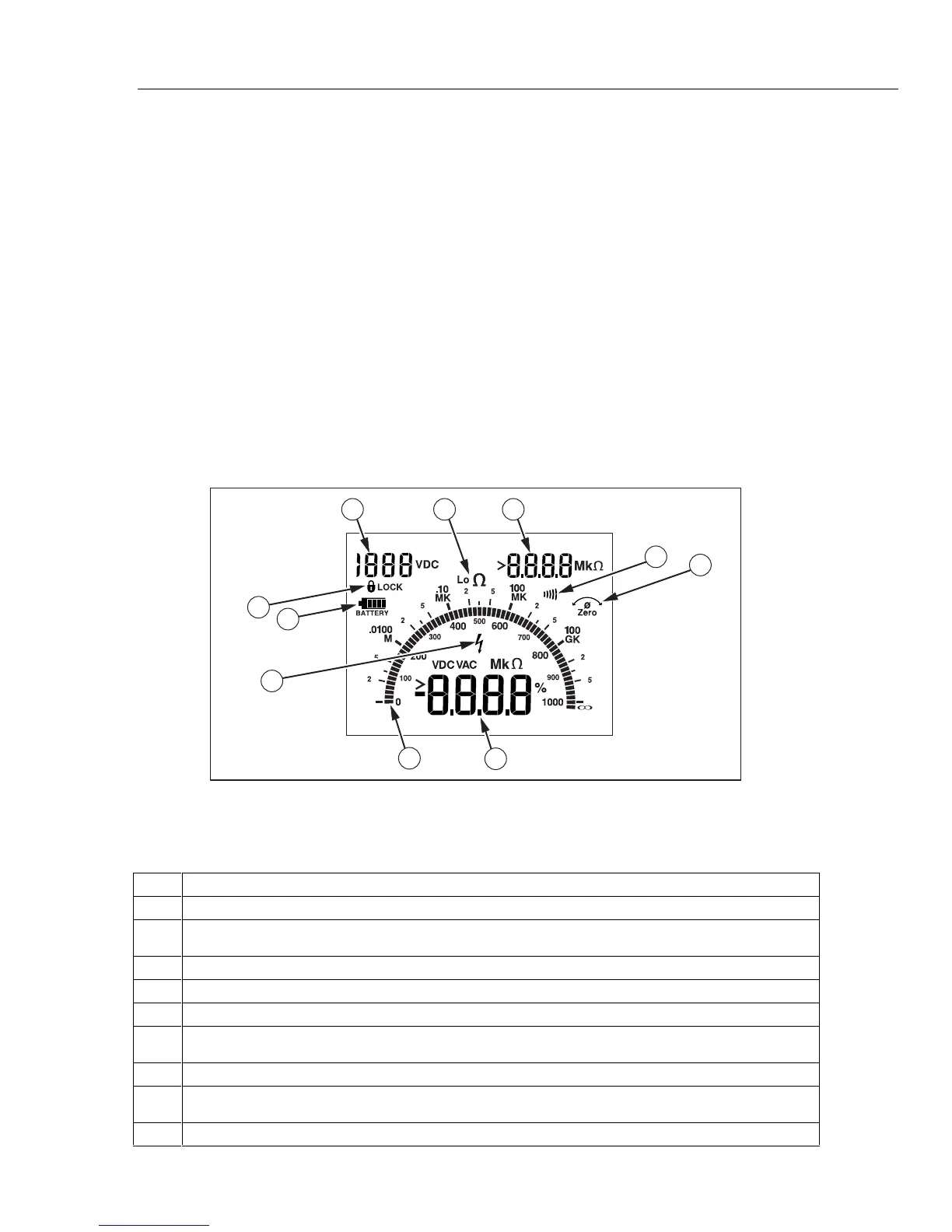
While turning the Meter on, push and hold down the beeper button. Compare the display
with the example in Figure 1. Check all segments for clarity and contrast.
1 32
6
7
9
10
8
4
5
acf12f.eps
Figure 1. Display
Table 3. Display Icons
A Voltage applied to the probes in Insulation Resistance function.
B Low Resistance/Resistance function indicator.
C Resistance reading held from the last measurement in Insulation Resistance or Low Resistance
function.
D Beeper symbol shows if beeper function is turned on in Resistance function.
E Zero symbol is on if test leads are zeroed out.
F Main reading display for all functions.
G Analog bar graph displays resistance on a logarithmic scale and voltage on a linear scale. The
value always tracks the main reading.
H High voltage warning symbol flashes if voltage ≥ 30 V ac or dc is present on the probes.
I Battery life indicator. Displays briefly when the Meter is first switched to a function. Displays the
amount of battery voltage left in increments of 25 %.
J Lock symbol is on if the TEST mode is locked in Insulation or Low Resistance functions.
 Loading...