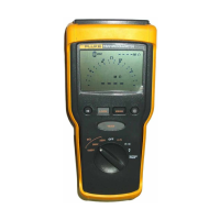
1520
Calibration Manual
8
Backlight Test
Push the backlight button and note that the all three backlight LEDs come on. Each LED
can be seen on the left side of the display as an intensified area.
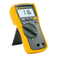
Battery Test
Turn the Rotary Switch to the Battery Check position and note that the batteries have
90% or better charge. Replace if necessary. Refer to "User Maintenance" for detailed
instructions on changing the batteries.
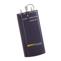
Discharge Circuit Test
The following Discharge Circuit Test is a safety related test that verifies input jack wiring
to the PCA, the RSOB contacts, RSOB pads on the PCA, and other active components on
the PCA.
Caution
DO NOT push the Meter TEST button during the following
procedure.
1. Connect the DMM to the VΩ and COM jack of the Meter.
2. Set the DMM to kΩ function.
3. Turn the Meter Rotary Switch to the 250V, 500V, 1000V and Lo Ω position. Check
that the DMM reading for each position is between 1600 and 2600 Ω.
Volts and Ohms Measurement Accuracy Verification
To verify accuracy of the V and Ω function, complete the following:
Perform the battery test and replace as necessary
1. Connect the Calibrator to the VΩ and COM inputs on the Meter.
2. Turn the Meter Rotary Switch to the function listed for each step of Table 4.
3. Apply the input for the steps 1 through 10 as listed in Table 4.
4. Compare the Meter displayed reading with the display limits of Table 4.
5. DISCONNECT THE CALIBRATOR FROM THE METER.
Table 4. Volts and Ohms Test
Display Reading
Step Function Source Output
Lower Limit Upper Limit
1 Volts 0 Volts -2 2
2 Volts 180 V 174 186
3 Volts 540 V 527 553
4 Volts 180 V @ 60 Hz 174 186
5 Volts 540 V @ 60 Hz 527 553
6 Ω 0 Ω 02
7 Ω 1200 Ω (UTTi High) 1174 1226
8 Ω 3600 Ω (UUTi High) 3526 3674
9 Ω Open >4000 >4000
10 Continuity on 27 Ω Beeper on Beeper on
 Loading...