Introduction
Design and Functions 1
1-9
grafikview2.eps
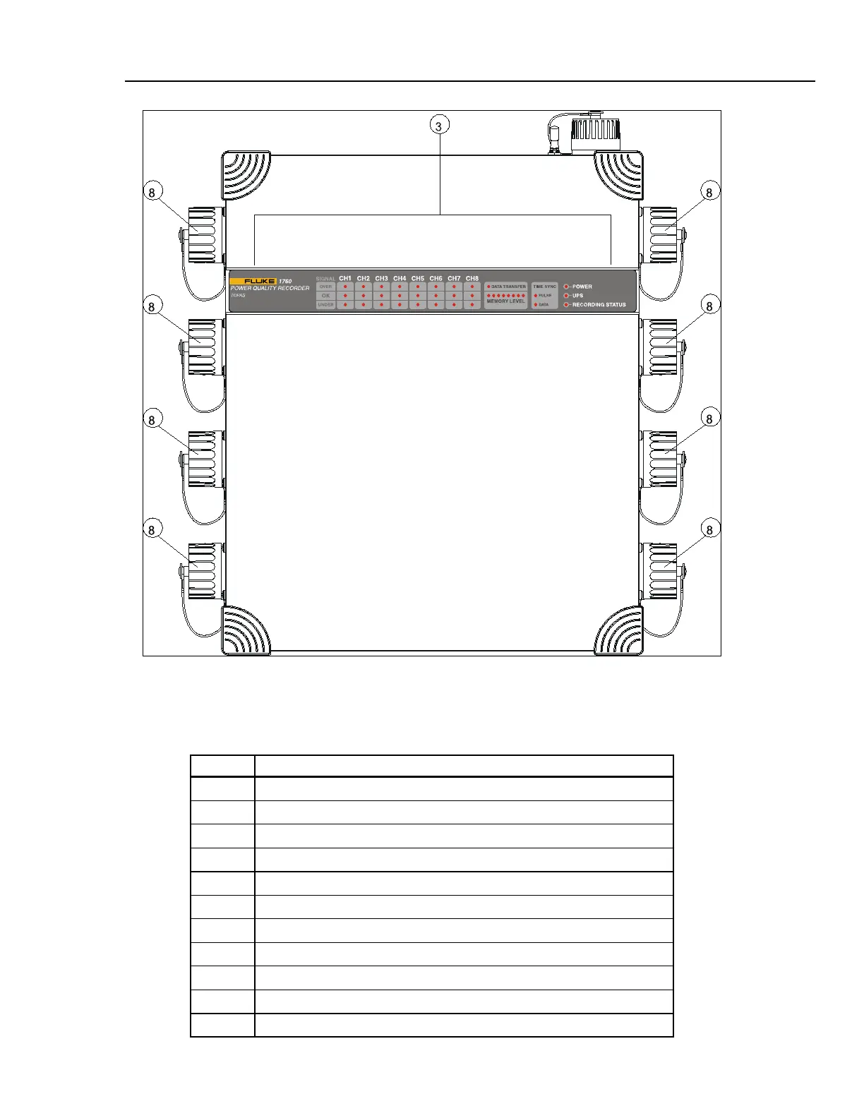
Figure 1-4. Front View
Table 1-2 shows the controls and indicators of the Recorder.
Table 1-2. Controls and Indicators
Sl No. Description
A
Mains connection.
B
Mains switch.
C
LED indicators.
D
Ethernet connector
E
USB connectors type A.
F
COM1 – serial port (RS232).
G
Feature connector (GPS, DCF 77, COM2, alarms, etc).
H
Measurement input connectors.
I
Compact Flash card slot.
J
Compact Flash eject button and LED
K
Reset button.