Operation
Connections to Measuring Circuits 3
3-11
Note
If this option (Calculation) is checked, you have to enter the phase-to-phase
voltage as the rated voltage V
N
in ‘Settings – Nominal / Limit Values’ (e.g.
400 V in the 230 V P-N network).
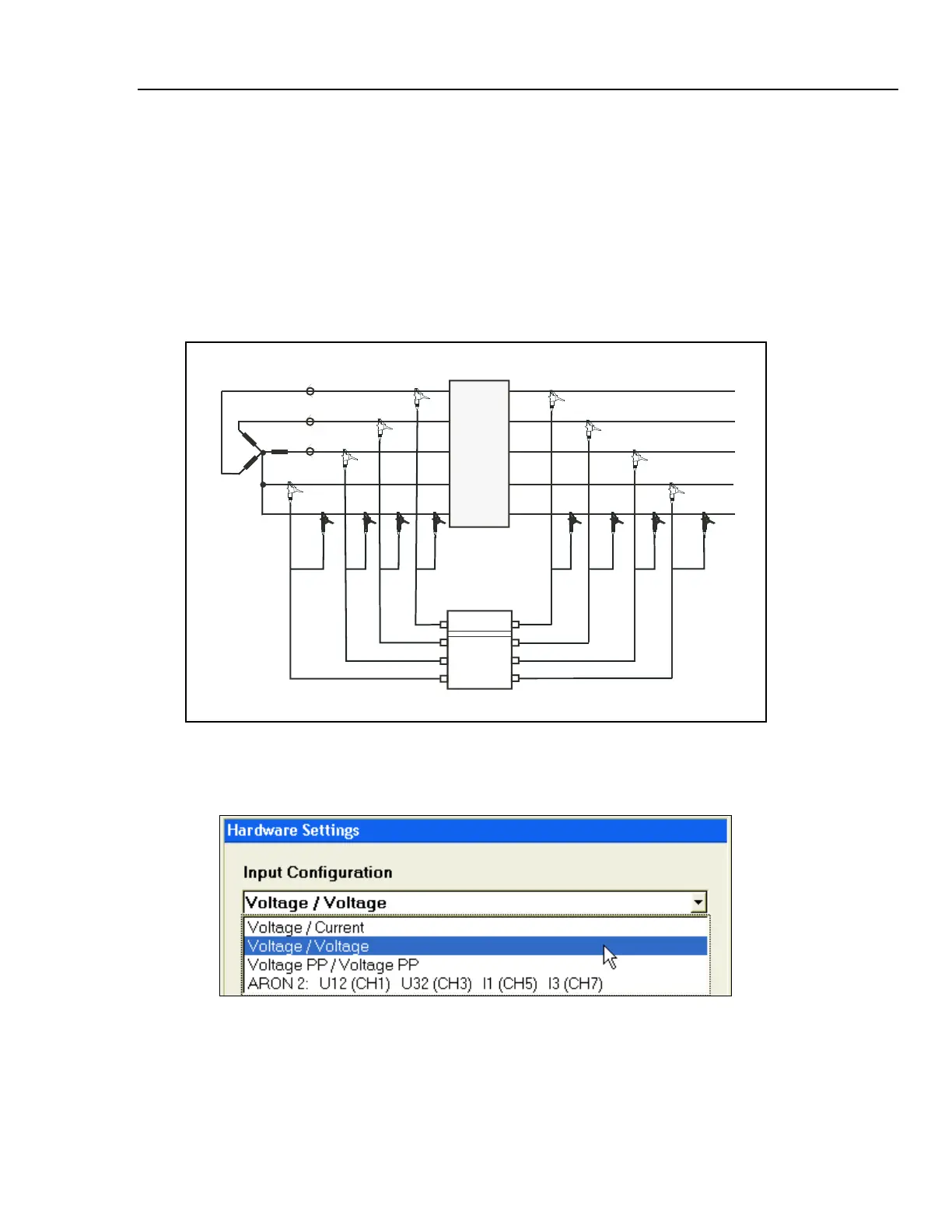
Two Star-Connected Voltage Systems
With this method, you can determine two phase voltages and the respective N conductor
voltages in two star connected three-phase systems.
Figure 3-6 shows the circuit diagram for 2-voltage system with neutral.
Fluke 1760
PEN
L2
L3
L1
L2
L3
L1
N
PE
Mains
System-U-U-Stern.eps
Figure 3-6. Circuit Diagram: 2 Voltage System with Neutral
Associated PC Software Settings:
messsystem2.bmp
Note
The power quality assessment according to EN50160 can be performed for
the phase voltages of system 1 and system 2 respectively; the preset limit
values apply to both evaluations.