True RMS Multimeter
Performance Tests
17
Keypad Test
To test the keypad, turn the Meter to AC V and push each button separately. Each button
push should cause the Meter to beep.
Reset the Meter by turning it
Off, and then back On.
Verification of the IR Communication Port
Note
If you are using MET/CAL to do performance testing, it is not necessary to
perform this verification test.
1. Connect the Infrared Serial Cable to the com port of a PC.
2. Connect the Infrared Serial Cable to the IR Cable Adapter and insert into the
187/189 accessory mount so that it is flush with the IR adapter window. Turn the
Meter rotary switch to DC V.
3. Install Fluke 87/89-IV, 187/189 Service Software, P/N 676152.
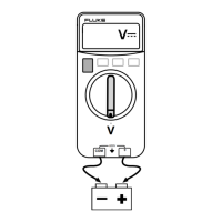
4. Apply 1 V dc to the
z input terminal.
5. The display reading should appear in text box of PC.
Note
If the PC indicates that the Meter is not connected, ensure that the com
port is correct and that the IR Serial Cable and adapter is aligned with the
IR window.
Testing Temperature
Connect K-type thermocouple and Fluke 80Ak to the temperature input on the Meter.
Connect the other end to the 5520A TC output. Allow connections to stabilize for 30
seconds before proceeding.
1. Turn the rotary switch to the temperature function.
2. Set the 5520A for K-type thermocouple and an output of 23 °C.
3. Enter the Meter Setup mode (press yellow button, then backlight button).
4. Adjust the temperature offset until the temperature on the Meter primary display
matches the 5520A output temperature (23 °C). Use the blue shift button and
backlight button to advance digit. Use the up and down arrow keys to edit digit.
5. Enter an offset value by pressing the yellow button, then the backlight button.
6. Exit Setup mode by pressing the yellow button, then the
CANCEL button.
7. Perform the steps in Table 3.
Table 3. Temperature Test Input and Display
Display
Input
Lower Limit Upper Limit
-10.0 °C -11.1 °C -8.9 °C
0.0 °C -1.0 °C1.0 °C
350.0 °C 345.0 °C 355.0 °C

 Loading...