187/189
Calibration Manual
22
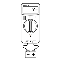
UP button
moves to the
next step
Autoranging
is disabled
for calibration
Function indicator
Calibration step number Input signal required Calibration mode indicator
aau01f.eps
Figure 6. Calibration Display
General Procedure
A sequence of signal inputs is required for each function that must be calibrated. The
secondary display shows the required input next to the step number for that function.
The primary display shows the value being measured. The measurement is likely to be
slightly different from the applied signal, because it may be showing an uncalibrated
measurement. The general calibration procedure is as follows:
1. Move the rotary switch to the function that you are calibrating.
2. Apply the input signal indicated by the secondary display.
3. Wait for the measurement on the primary display to settle out to its final value.
4. Press the
UP button to proceed to the next step. The Meter records a new constant.
5. Repeat steps 2 through 4 until the secondary display shows
End. This indicates that
the calibration procedure for this function is complete. New constants will not be
recorded until secondary display shows
End.
6. If there are more functions to be calibrated, move the rotary switch to the appropriate
function, and continue from step one. Otherwise, turn the rotary switch to the
OFF
position to exit calibration.
Note
DC mV calibration affects the calibration of ALL functions and AC mV
will affect all AC functions.
If the accuracy of the calibration source is more than approximately
15 % from the nominal value required for the cal point, then the factory
default cal constants will automatically be used instead of source value.
In this case, the Meter may not pass the verification test and may
require re-calibration.

 Loading...