Digital Multimeters
Calibration Adjustments
15
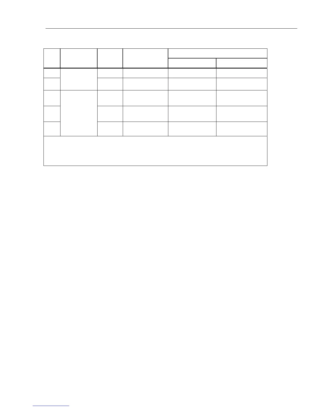
Table 3. Accuracy Tests (cont.)
Display Reading
Step
Test
Function
Range 5520A Output
27 II 28 II
52
0 °C N/A -1.0 to 1.0
53
mVdc
Temperature
4
– 28 II
100 °C N/A 98.0 to 102.0
54 Press backlight
button
Backlight comes
on
Backlight comes on
55 Press backlight
button
Backlight
intensifies
Backlight intensifies
56
Backlight
Press backlight
button
Backlight goes off Backlight goes off
[1] Remove test leads from unit.
[2] Use REL to compensate for internal Meter and lead capacitance (must disconnect test leads from calibrator before pushing REL)
[3] The Meter accuracy is not specified at this input signal frequency with Low-pass filter selected. The display reading shown, checks
that the Low-pass filter is active and follows an expected roll-off curve.
[4] To ensure accurate measurement, the Meter and thermocouple adapter must be at the same temperature. After connecting the
thermocouple adapter to the Meter allow for reading to stabilize before recording display reading.
Calibration Adjustments
Perform the Calibration Adjustment Procedure if the Meter fails any performance tests. If
the adjustment routine is discontinued prior to completion, no changes are made to the
calibration contstants that are stored in memory. The following is an explanation of the
pushbutton features and requirements to enter the CAL mode.
Cal Mode Pushbutton Functions
• The CAL mode will be initiated by holding down the MINMAX pushbutton at power
up and entering a four digit password.
• The AutoHOLD pushbutton will act as an "ENTER" key and will advance through
the CAL initiation and adjustment procedure steps.
• The pushbuttons are used to select a four-digit password.
During initiation of the CAL mode, a display count will show how many times
calibration constants have been written to memory.
Entering and Displaying the Four-Digit Password
When the Meter was manufactured it was given a default password of 1234. The
following pushbuttons are used to select the password. Each pushbutton represents the
indicated digit.
Yellow = 1 MINMAX = 2 RANGE = 3 AutoHOLD = 4
Backlight =5 Continuity = 6 REL = 7 Hz = 8
After selecting the password the user has two choices:
Pressing AutoHOLD will display "C-01" which indicates correct password and
successful entry. You may now proceed with the first calibration step.
Pressing RANGE will display "----", which indicates correct password, proceed to
select a new password.
If the password is incorrect, the concluding AutoHOLD or RANGE pushbutton press will
instead cause the Meter to double beep and the display will show "????". The password
entry process was unsuccessful and can be tried again or you may exit this mode by
turning the Meter off.

 Loading...