Theory of Operation
Block Diagram Description
2
2-5
conversions occur every 40 ms (each at 1/10th the desired resolution) without taking
time for an autozero phase between the conversions. These minor conversions (or
samples, as they are called in the following discussion) occur at a rate of 25 per second,
and are used to provided the fast response bar-graph display and fast autoranging.
New samples are taken every 40 ms. Ten samples are summed to produce a full-
resolution digital display, with full scale greater than 3200 counts. A 100 ms autozero
phase occurs every 10-sample sequence.
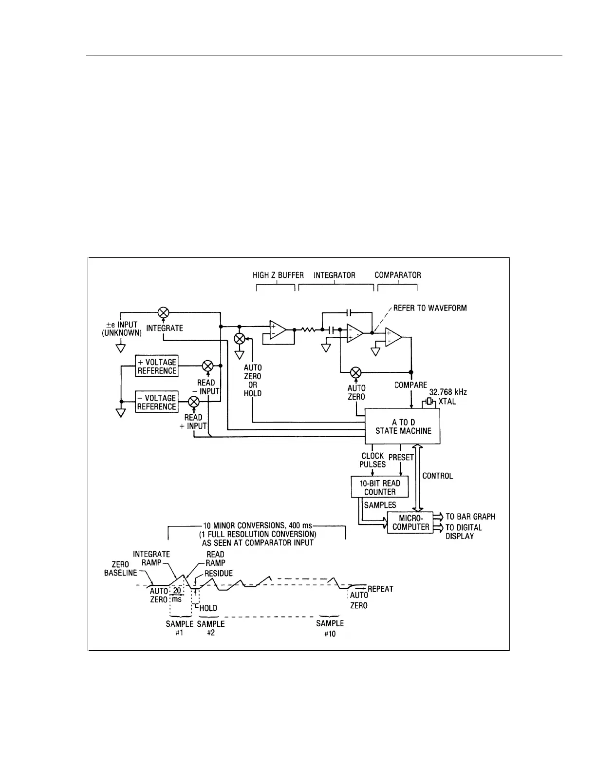
Basic A/D conversion elements and waveforms are illustrated in Figure 2-2. As this
figure shows, a residual charge is retained by the integrator capacitor due to the
overshoot past the true-zero base line. In the absence of an autozero phase, the residual
charge would normally produce a significant error in the sample next taken. However, a
digital algorithm eliminates the error and accounts for the residue as it propagates
through all 10 samples.
aac02s.tif
Figure 2-2. A/D Conversion Elements and Waveform
Digital circuitry in U1 provides state machine control for the A/D converter, a read
counter for A/D samples, decoding ROMs for analog switch drive and for read counter
 Loading...