Maintenance
Calibration Adjustment
3
3-15
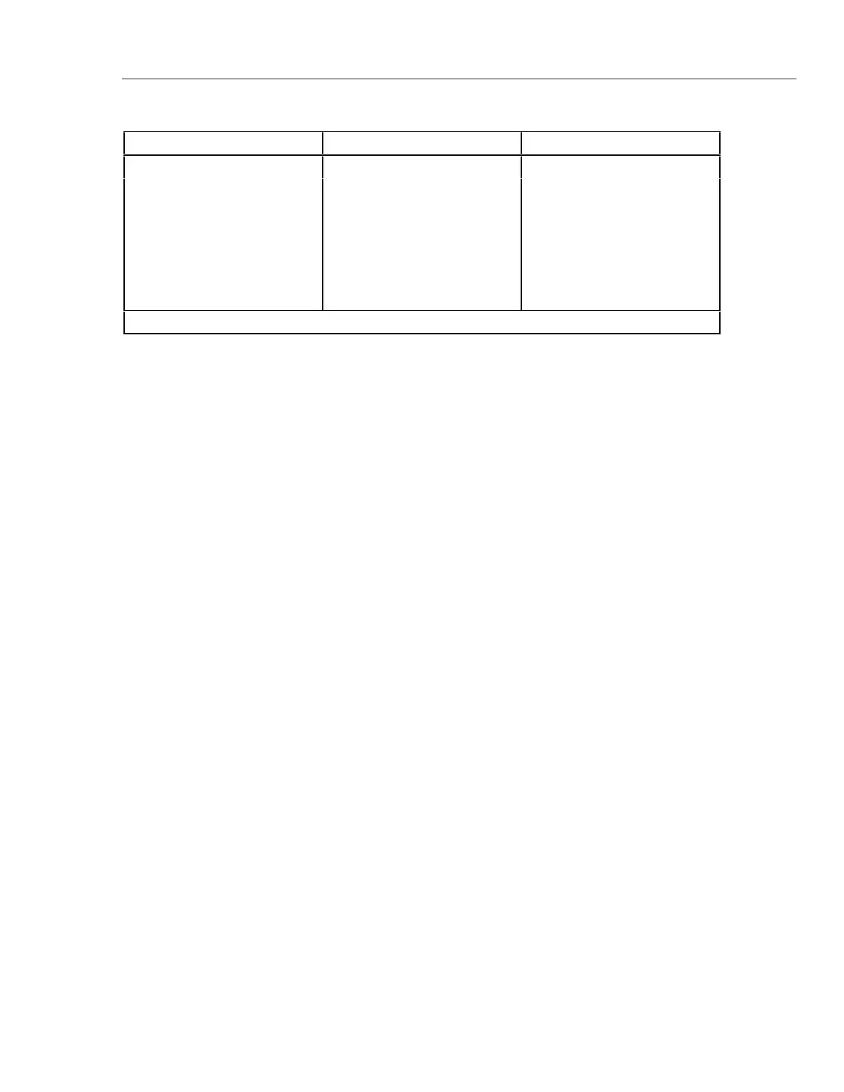
Table 3-3. Ohm Function Performance Test
Step Resistance Indication
1 100 J 99.5 to 100.5
2 1.000 kJ .997 to 1.003 k
3 10.00 kJ 9.97 to 10.03 k
4 100.0 kJ 99.7 to 100.3 k
51 MJ .997 to 1.003 M
6 10 MJ 9.89 to 10.11 M
*7 open circuit -00.10 to .0010 nS
*Note: Conductance (nS) range must be entered using manual range selection.
3-17. Diode Test Performance Verification
The following procedure may be used to verify proper operation of the diode test
function. (This test can not be performed unless the source can sink 0.6 mA at 0.9 V.)
1. Turn the UUT function selection switch to the diode test function.
2. The UUT should display OL.
3. Connect the DMM Calibrator to the UUT volt/ ohms/ diode-test input terminal and
common, and switch on Calibrator power.
4. Program the DMM Calibrator output for 1.00 V, then push the Range Lock button on
the Calibrator to place the Calibrator in the 3.3V range.
5. Program the DMM Calibrator output for 0.090 V and verify that the UUT indicates
approximately 0.090 V and the beeper is sounding continuous tone.
6. Increase the DMM Calibrator output to 0.11 V. The beeper should turn off.
7. Increase the Calibrator output to 1.0V, then slowly decrease the Calibrator output to
0.6 V. Note that the UUT beeper produces a short beep as the voltage descends
through 0.7 V (typical silicon diode threshold).
8. Push the DMM Calibrator Range Lock button to return to Autorange operation.
3-18. Calibration Adjustment
Under normal operating conditions, the Fluke 27 should maintain its specifications for a
period of one year after calibration. If the instrument has been repaired, or if it has failed
any of the performance tests, the following calibration adjustment procedures must be
performed. Use a non-conductive tool for adjustments.
Note
In the following procedures, the Fluke 27 is referred to as the unit under
test, or UUT.
3-19. Calibration Preparation
Allow the UUT to stabilize at an ambient temperature of 21 to 25 degrees Celsius (70 to
77 degrees Fahrenheit) and at a relative humidity of less than 80% with the power off for
at least 30 minutes before beginning calibration. Calibration adjustments require removal
of the bottom cover. Complete steps 1 through 7 of the disassembly procedure given
earlier in this chapter, and then reconnect the battery to the UUT’s battery connector.