Maintenance
Troubleshooting
3
3-19
6. Check the active filter output (pin 29 of U1) for approximately 200 mV dc. If 200
mV is not present, R13, R16, C18, or C19 may be defective. (Measurement may be
affected by loading.)
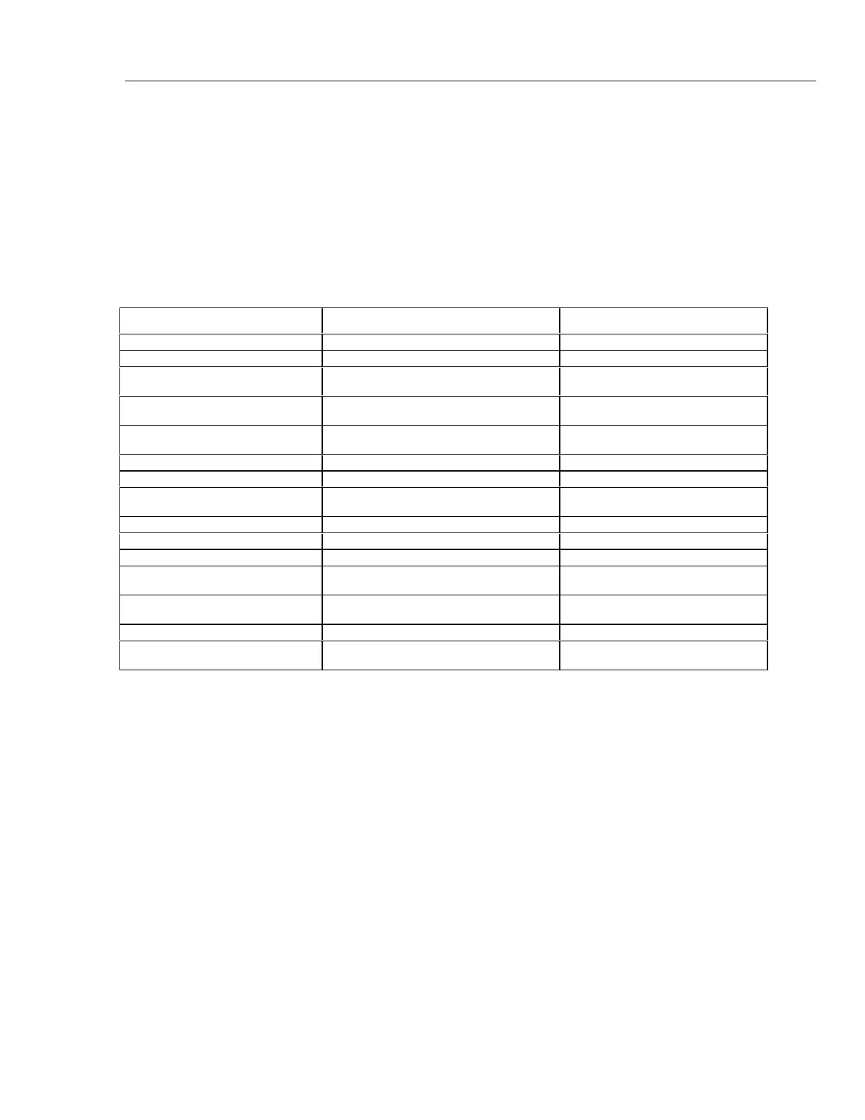
3-26. Fault Diagnosis Guide
Table 3-3 presents a fault diagnosis guide for the Fluke 27. The left column lists various
malfunction. The left column lists various malfunction symptoms. The center column
recommends actions to determine the exact problem. The right column lists the
components most likely to be defective.
Table 3-4. Fault Diagnosis Guide
Symptom Recommended Action Possible Component
Blank display Do system check given in paragraph 3-24. BT1, U1,U2,Y1,C13
Display reads zero in volt dc Do do signal tracing in paragraph 3-25. RT1,Z1,U1,S1
Display hangs up in self-test mode Do system check given in paragraph 3-24. R15, R18, R19, R12, R37, VR1, Z1,
U1, C20, C21
Display reads OL or 0 in 320 mA
range
R9, R10, U1
Display reads 0 in 320 mA or 10A
ranges
F1, F2, R9, R20, R14
AC volts is inaccurate Check calibration R31, R32, R29, R30
320 mV range reads OL Q11, U1
AC volts measurement noisy at
50-60 Hz
R13, R16, C18,C19
Wrong annunciator displayed S1R, U1
Volts inaccurate Check calibration RV2-RV5
Ohms inaccurate Z1, U1
Intermittent display Clean connectors and connector strips on
LCD and pca
Display Assembly
Display reads constant offset in
volts
C18, C19, C20 shorted
Ohms reads low or will not read OL Q1,Q2 shorted or leaky
Ohms reads random or alternates
between
R2, RT1