True-rms Digital Multimeters
Detailed Specifications
9
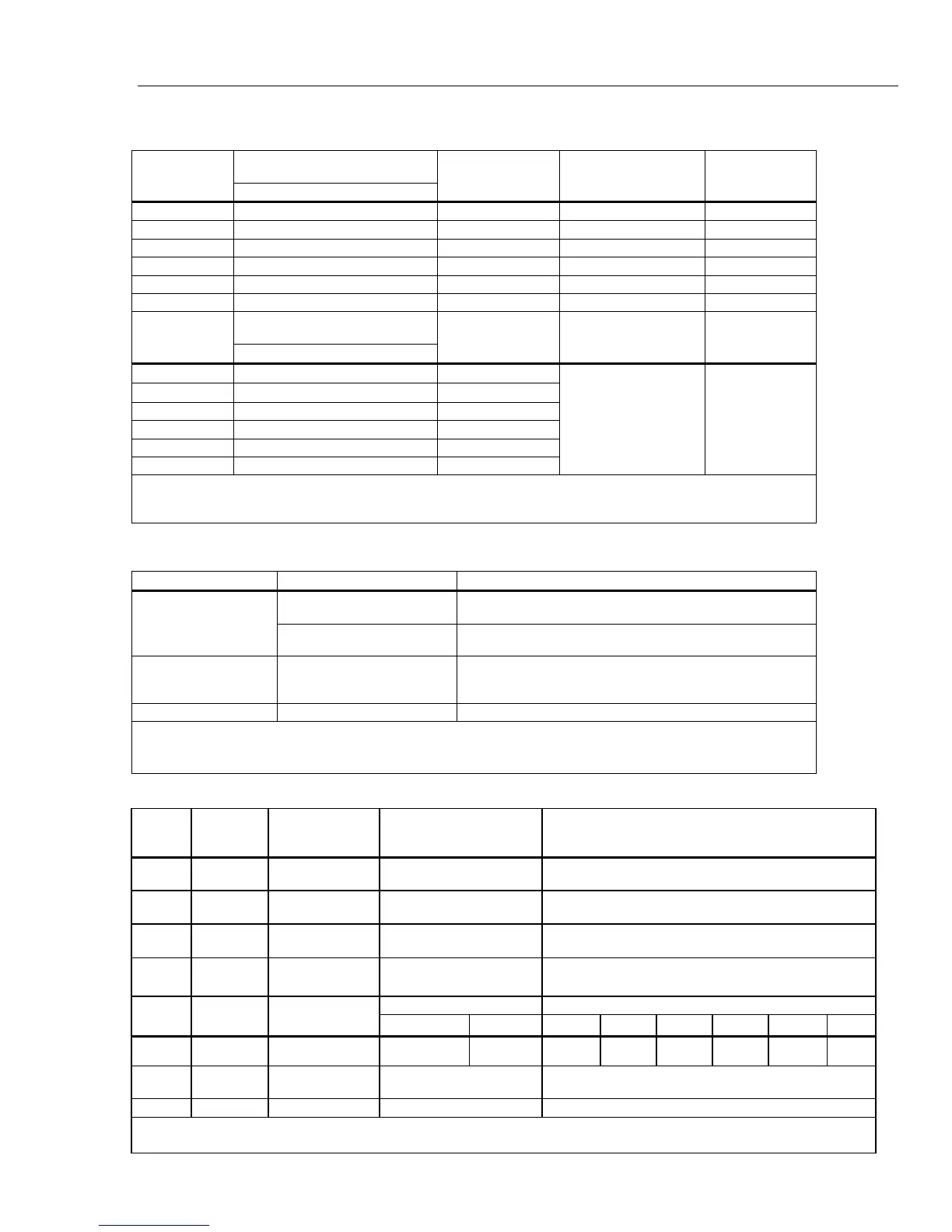
Frequency Counter Sensitivity
Approximate Voltage Sensitivity
(rms sine wave)
[1]
Input Range
15 Hz to 100 kHz
AC Bandwidth
[2]
Approximate DC
Trigger Levels
DC Bandwidth
[2]
50 mV 5 mV 1 MHz 5 mV & 20 mV 600 kHz
500 mV 25 mV 1 MHz 20 mV & 60 mV 1 MHz
5 V 0.25 V 700 kHz 1.4 V & 2.0 V 80 kHz
50 V 2.5 V 1 MHz 0.5 V & 6.5 V 1 MHz
500 V 25 V 300 kHz 5 V & 40 V 300 kHz
1000 V 50 V 300 kHz 5 V & 100 V 300 kHz
Approximate Current Sensitivity
(rms sine wave)
Input Range
15 Hz to 10 kHz
AC Bandwidth
Approximate DC
Trigger Levels
DC Bandwidth
500 μA 25 μA
100 kHz
5000 μA 250 μA
100 kHz
50 mA 2.5 mA 100 kHz
400 mA 25 mA 100 kHz
5 A 0.25 A 100 kHz
10 A 1.0 A 100 kHz
NA NA
[1] Maximum input = 10 x range (1000 V maximum, 2 x 10
7
V-Hz product maximum). Noise at low frequencies and amplitudes may
affect accuracy.
[2] Typical frequency bandwidth with full scale (or maximum 2 x 10
7
V-Hz product) rms sine wave.
MIN MAX, Recording, and Peak Specifications
Function Nominal Response Accuracy
200 ms to 80% (dc function)
Specified accuracy ±12 counts for changes >425 ms in
duration in manual range.
MIN MAX, Recording
350 ms to 80 % (ac function)
Specified Accuracy ±40 counts for changes >1.5 s in duration
in manual range.
Peak
250 μS (peak)
[1]
Specified accuracy ±100 counts
[2]
up to 5,000 count (full
range) reading. For higher peak reading (to 12,000 counts),
specified accuracy ±2 %
[3]
of reading.
Crest Factor 350 ms to 80 % For periodic waveforms from 50 to 440 Hz ± (4 % + 1 count).
[1] For repetitive peaks; 2.5 ms for single events. Peak not specified for 500 µA DC, 50 mA DC, 5 A DC.
[2] 200 counts in 500 mV AC, 500 μA AC, 50 mA AC, 5 A AC.
[3] 3 % in 500 mV AC, 500 μA AC, 50 mA AC, 5 A AC.
Input Characteristics
Function
Overload
Protection
[1]
Input Impedance
Common Mode
Rejection Ratio
(1 kΩ unbalance)
Normal Mode Rejection
L
1000 V
10 MΩ <100 pF
>120 dB at dc,
50 Hz or 60 Hz
>60 dB at 50 Hz or 60 Hz
F
mV
1000 V
[2]
10 MΩ <100 pF
>120 dB at dc,
50 Hz or 60 Hz
>60 dB at 50 Hz or 60 Hz
K
1000 V
10 MΩ <100 pF
(ac-coupled)
>60 dB, dc to 60 Hz
L
1000 V
3.2 kΩ <100 pF
(ac-coupled)
Not specified Not specified
Full Scale Voltage Typical Short Circuit Current
Function
Overload
Protection
[1]
Open Circuit
Test Voltage
To 500 kΩ
>5 or 50 nS
500 Ω 5 kΩ 50 kΩ 500 kΩ 5 MΩ 50 MΩ
e
1000 V
[2]
5 V dc 550 mV <5 V 1 mA
100 μA 10 μA
1 μA 0.3 μA 0.3 μA
50e 1000 V
[2]
20 V decreasing
to 2.5 V
500 mV 10 mA
G
1000 V
[2]
5 V dc 3.1 V dc 1 mA
[1] Input is limited to the product of a V rms sinewave times frequency of 2 x 10
7
V-Hz.
[2] For circuits <0.5 A short circuit. 660V for high energy circuits.

 Loading...