True-rms Digital Multimeters
Performance Tests
17
1. Turn the Meter on and position the rotary switch to N and select the temperature
function. Select the degrees C function key.
2. On the Meter, select Offset. Adjust the offset to 000.0 using keypad edit buttons.
3. Close the Offset window.
4. Set the 5520A for K-type thermocouple and an output of 0 °C.
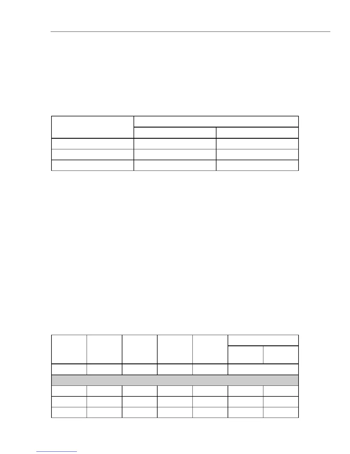
5. Perform the measurement steps in Table 3.
Table 3. Temperature Test Input and Display
Display
Input
Lower Limit Upper Limit
0.0 °C -1.0 °C 1.0 °C
100.0 °C 98.0 °C 102.0 °C
1000.0 °C 989.0 °C 1011.0 °C
Accuracy Tests for Volts, Current,
Ω
,
E
, and
G
Test Functions
To verify the accuracy of Meter functions, do the following:
1. Connect the Calibrator Normal terminals to the Meter’s V and COM input terminals.
2. Turn on the Meter.
3. Turn the rotary switch to N.
Note
The DC mV measurements in Table 4 are subject to offsets caused by
thermals due to temperature gradients between connecting materials. After
connecting the calibrator to the Meter terminals, allow time (could be
several minutes) for the thermals to dissipate. When readings are stable,
perform a REL and record the Meter reading.
4. Apply the Input Level and frequency for step 1 of Table 4.
5. Compare the Meter’s display reading with the Display Limits in Table 4.
6. If the display reading falls outside of the Display Reading Limits shown in Table 4,
the Meter does not meet specification and requires adjustment or repair.
7. Complete the remaining test steps for each function listed in Table 4.
Table 4. 287/289 Performance Test Steps
Display Reading
[1]
Step Function Range Input Level
Frequency
or Model
Lower
Limit
Upper
Limit
1. DC mV 50.000 mV 0 mV Allow reading to stabilize
REL Offsets
2. DC mV 50.000 mV 0 mV
[2]
-0.020 0.020
3. DC mV 50.000 mV 0.025 mV
[2]
0.005 0.045
4. DC mV 50.000 mV -0.025 mV
[2]
-0.045 -0.005

 Loading...