287/289
Calibration Manual
26
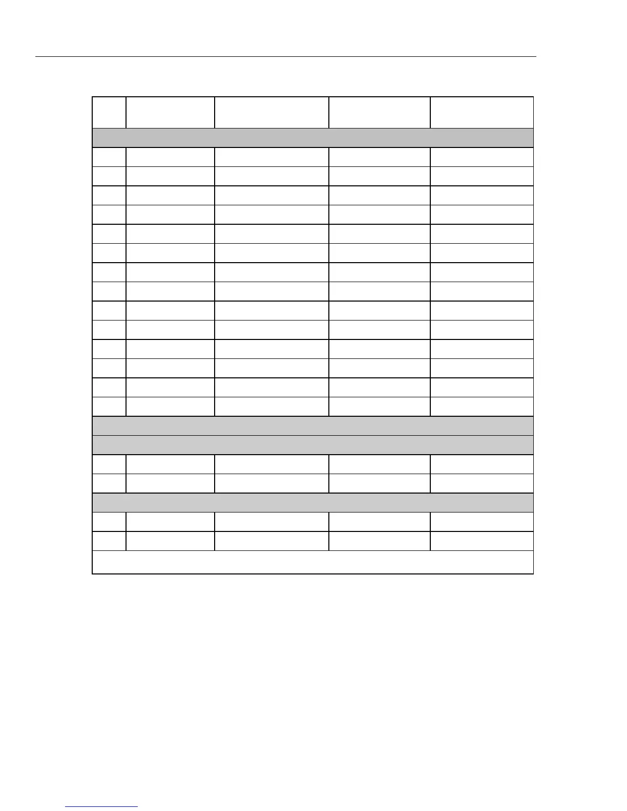
Table 7. Calibration Adjustments Steps (cont.)
Step
Rotary Switch
Position
Source Value
Settling Time
(seconds)
Calibrating Time
[1]
(seconds)
Connect the 5520A in a 4-Wire configuration and select COMP 2-Wire
39 Diode Test 0 Ω, zcomp wire2 2 2
40 Diode Test 3.1 V, 0 Hz 2 2
41 μA DC 500.0 μA, 0 Hz 3 4
42 μA DC 5000.0 μA, 0 Hz 3 4
43 μA AC 500.0 μA, 60 Hz 10 4
44 μA AC 5000.0 μA, 60 Hz 10 3
45 mA DC 50.0 mA, 60 Hz 5 4
46 mA AC 400.0 mA, 0 Hz 3 4
47 mA AC 50.0 mA, 60 Hz 10 3
48 mA AC 400.0 mA, 60 Hz 10 4
49 ADC 5.0 A, 0 Hz 8 4
50 ADC 10.0 A, 0 Hz 3 2
51 AAC 5.0 A, 60 Hz 10 4
52 AAC 10.0 A, 60 Hz 9 4
Connect the 5520A in a 4-Wire configuration and select COMP 2-Wire
To reduce settling time, apply 10 ohms to Meter before setting Rotary Switch to LoΩ
53 LoΩ (289) 10.000 Ω 30 2
54 LoΩ (289) 50.000 Ω 15 3
Disconnect 5520A 4-Wire configuration and turn COMP off
55 LoZ (289) 10.0 V, 0 Hz 2 2
56 mV AC (289) 500.00 mV, 60 Hz 5 5
[1] Meter is “Calibrating” after “Next” is pressed.
[2] For software version 1.00, the instrument display indicates 60 kHz. Use 65 kHz.

 Loading...