2352 Walsh Ave. Santa Clara, CA 95051. U. S. A. Tel.: (408) 748-9100, Fax: (408) 748-9111 www.analogtechnologies.com
Copyrights 2000 – 2012, Analog Technologies, Inc. All Rights Reserved. Updated on 11/22/2012 7
nalog Technologies
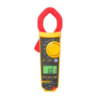
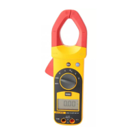
317 and 319
Clamp Meter
When making current measurements, disconnect the test leads from the clamp meter.
Keep fingers behind Tactile Barrier. See table 4.
Note
When measuring current, center the conductor in the clamp using the alignment marks on the clamp. See table 4.
Zero
Before taking DC measurements, zero the clamp meter to ensure correct readings. Zeroing the clamp meter removes DC offset
(ambient noise) from the reading.
Note
Before zeroing the clamp meter, make sure the jaws are closed and there is no conductor between them.
To zero the clamp meter, press
.
MEASURING AC OR DC CURRENT
To measure AC or DC current:
1. Turn the rotary function switch to the proper current range.
2. Press
to select DC current if necessary. The default is AC current.
3. If measuring DC, wait for the display to stabilize and then press
to zero the clamp meter.
Note: Before zeroing the clamp meter, make sure the jaws are closed and there is no conductor between them.
4. Open the clamp by pressing the jaw release and insert the conductor to be measured into the clamp.
5. Close the clamp and center the conductor using the jaw alignment marks.
6. View the reading on the LCD.
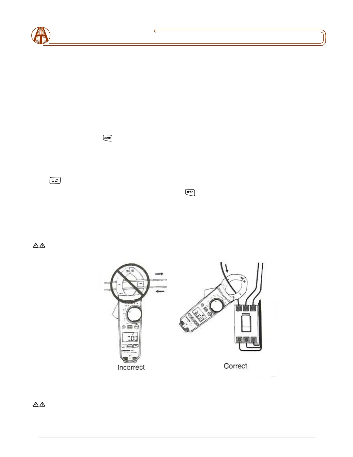
Warning: To avoid possible electric shock or personal injury, currents moving in opposite directions cancel each
other. Place only ONE conductor into the clamp at a time, see figure 5.
Figure 5. Connecting the Clamp Meter
MEASURING AC AND DC VOLTAGE
Warning
To avoid electric shock or personal injury:
 Loading...