2352 Walsh Ave. Santa Clara, CA 95051. U. S. A. Tel.: (408) 748-9100, Fax: (408) 748-9111 www.analogtechnologies.com
Copyrights 2000 – 2012, Analog Technologies, Inc. All Rights Reserved. Updated on 11/22/2012 9
nalog Technologies
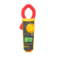
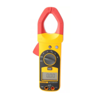
317 and 319
Clamp Meter
Figure 8. Measuring Resistance
TESTING CONTINUITY
Warning
To avoid electrical shock when testing continuity in a circuit, make sure the power to the circuit is turned off and all capacitors
are discharged.
To test continuity:
1. Remove power from the circuit being tested.
2. Turn the rotary function switch to
.
3. Connect the black test lead to the COM terminal and the red test lead to the
terminal.
4. Connect the probes across the circuit or component to be tested. See figure 9.
5. If the resistance is <30Ω, the beeper sounds continuously denoting continuity. If the display reads OL, the circuit is open.
Figure 9. Measuring Continuity
Warning
To avoid electrical shock or personal injury, do not touch the terminals while measuring. Dangerous voltages can be
present at the input terminals but not displayed.
 Loading...