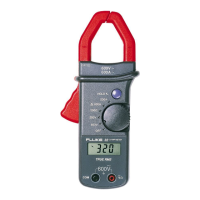
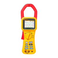
Power Quality Clamp Meter
Calibration Adjustment
17
Calibration Adjustment Procedure
Note
Before calibration, ensure that the instrument clamp is degaussed up to a
minimum of 1000 A.
The calibration mode steps are listed in Table 3. Make sure the date and time are set to
the current date and time. VOLTS CAL and AMPS CAL are independent, calibration
constants are saved at the end of each section.
Table 3. Calibration Mode
State Key Action Comments
First
Calibration
Screen
R
H
E
M
F
G
JK
Screen for S6:
VOLTS CAL – REC
AMPS CAL – HOLD
CONTRAST – SAVE
SELF-TEST – MENU
DATE & TIME – left arrow
CLEAR FLASH – right arrow
EXIT – down arrow, up arrow
EXIT to normal operation.
V1 R “Apply 0V”
“Press <RUN> when ready”
Next State: V2
Connect Calibrator Hi to
345 V
Connect Calibrator Lo to
345 COM
V2 H Screen for V2:
“VOLTS OFFSETS”
“V to ASIC V” – hex value
“V to ASIC A” – hex value
“V SCF” – hex value
“A SCF” – hex value
On completion:
“Press <RUN> when ready”
Next State: V3
V3 H “VOLTS COMMON MODE”
“APPLY 10V AC 400Hz
between V and COM
connected together and 0V”
“Press <RUN> when ready”
Next State: V4
Connection instruction on
the unit is incorrect. Do not
open the battery door.
Maintain the 0 V from
previous step, press <RUN>.
 Loading...