c.
Radio Frequency Interference
can
be
particularily
troublesome
with
low-current
thermoelements.
The
thermocouple in the Model 540B
is
incased
in
a
steel
shield
to
minimize
stray
field
pick
- up.
However,
to
insure
accuracy,
the
Model 540B
should
be
used
in
areas
of
relatively
low
field
strength.
d. The number of
transfers
will
vary
with the degree
of
accuracy
required.
In
general
it
is
suggested
that
three
seperate
transfers
(de to
ac
and back
to
de constitutes one
transfer)
be
made for any single
measurement. This will be adequate only if a good
degree
of
repeatability
is
achieved. Difficulty in
repeating
any
measurement
can
be
caused
by any
number
of
problems,
the
most
common of which
are
poor collllections, unstable
sources,
and
inter-
ference
from
stray
capacitance
or
energy
fields.
Any
factor
which
detracts
from
repeatability
must
be
eliminated
before
accurate
transfers
can
be
made.
e.
All
of
the
components and
elements
in the Model
540B have been selected
to minimize environmental
sensitivity.
It
is
suggested that the Model 540B be
given
time
enough to
arrive
at
the
environmental
temperature
before
it
is
used.
If
the Model 540B
is
used
before
it
has
arrived
at
the
temperature
of
the
environment
where
it
is
to
be
used,excessive
thermal
drift
will
be
observed
making
accurate
transfers
more
difficult.
f. The Model 540B imposes
two
load conditions on
the
ac
source.
The
ac
source
sees
the
182
ohms/volt
input impedance of the Model 540B when
the
MODE
switch
is
in the
AC
TRANSFER position. When the
MODE
switch
is
in
the
OFF
or
DC
TRANSFER
positions,
the
ac
source
sees
the
Model 540B
as
an
open
cir
c
uit.
This
impedance
change
across
the
ac
source
causes
a corresponding output
level
change
from
the
ac
source
. When
calibrating
a
device that
is
quite sensitive to
level
changes, the
user
should determine
if
the ac source level changes
could adversely affect the device. The
user
should
take appropriate precautions, such
as
switching the
device out of the calibration
circuit
before turning
the
MODE
switch
to
the
OFF
or
DC
positions,
should such a situation
arise
.
g.
Though the internal range selection components
and
thermocouple in the Model 540B
are
protected
from
overloads in
the
voltage mode;
no
protection
is
pro-
vided in the
current
mode
or
for external shunts
or
high
frequency
converters.
These
devices
are
easily
damaged
or
destroyed
by
overloads
and
all
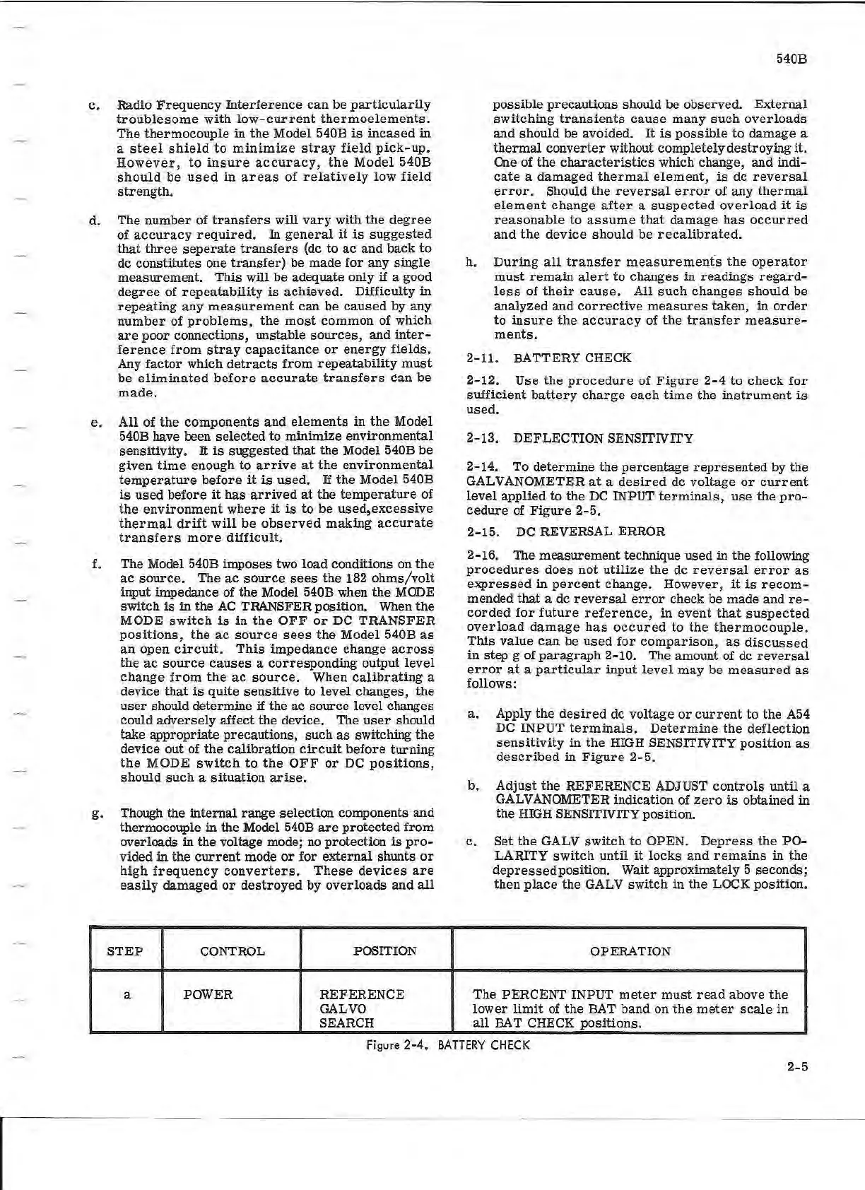
STEP
CONTROL
POSITION
a POWER
REFERENCE
GALVO
SEARCH
540B
possible precautions should
be observed. External
switching
transients
cause
many
such
overloads
and should be avoided.
It
is
possible
to
damage a
thermal
converter without completely destroying it.
One
of the
characteristics
which change, and indi-
cate
a
damaged
thermal
element,
is
de
reversal
error.
Should
the
reversal
error
of any
thermal
element
change
after
a
suspected
overload
it
is
reasonable
to
assume
that
damage
has
occurred
and
the
device
should be
recalibrated.
h.
During
all
transfer
measurements
the
operator
must
remain
alert
to
changes in readings
regard-
less
of
their
cause.
All
such
changes should be
analyzed and
corrective
measures
taken, in
order
to
insure
the
accuracy
of
the
transfer
measure-
ments.
2-11. BATTERY CHECK
2- 12. Use
the
procedure
of
Figure
2-4
to check
for
sufficient
battery
charge
each
time
the
instrument
is
used.
2-13. DEFLECTION SENSITIVITY
2-14. To determine the percentage
represented
by the
GALVANOMETER
at
a
desired
de voltage
or
current
level
applied
to
the
DC
INPUT
terminals,
use the
pro
-
cedure
of
Figure
2-
5.
2-15.
DC
REVERSAL ERROR
2-16. The measurement technique used in the following
procedures
does
not
utilize
the de
reversal
error
as
expressed
in
percent
change. However,
it
is
recom-
mended that a de
reversal
error
check be made and
re
-
corded
for
future
reference,
in event
that
suspected
overload
damage
has
occured
to
the
thermocouple.
This
value
can
be
used
for
comparison,
as
discussed
in step g of paragraph 2-10. The amount of de
reversal
error
at
a
particular
input
level
may be
measured
as
follows:
a. Apply the
desired
de voltage
or
current
to the
A54
DC
INPUT
terminals
.
Determine
the
deflection
sensitivity
in
the
HIGH
SENSITIVITY
position
as
described
in
Figure
2- 5.
b.
Adjust
the
REFERENCE ADJUST
controls
until a
GALVANOMETER indication of
zero
is
obtained in
the
HIGH
SENSITIVITY position.
c. Set the GALV switch to OPEN.
Depress
the
PO-
LARITY
switch
until
it
locks and
remains
in the
depressedposition. Wait approximately
5 seconds;
then
place
the GALV switch in
the
LOCK position.
OPERATION
The PERCENT INPUT
meter
must
read
above
the
lower
limit
of
the
BAT
band on
the
meter
scale
in
all
BAT
CHECK positions.
Figure 2-4.
BATTERY
CHECK
2-5