3-17.
Resetting
the
Protection
Amplifier
is
accom-
plished
by cutting off the voltage
to
it. It
is
always
ad-
visable to determine the cause of the overload before
at-
tempting
to
reset
the
circuit.
The voltage
may
be
cut-
off
to
the
Protection
Amplifier
by two
methods.
The
MODE
switch may be
placed
in
the
OFF position and
the
POWER
switch
may
be
operated
to
any
position
other
than
ON.
Either
of
these
actions
will
cause
an
inter-
ruption
in
the
battery
power to
the
Protection
Amplifier.
The
preferred
method
is
resetting
the
protection
cir-
cuit
with
the
MODE
switch.
3-1
.8. A
push
button,
momentary
open,
switch
called
PROTECTION DISABLE
is
located on
the
front
panel
of
the
Model A54- 2
plug-in
unit.
This
switch,
and
its
function,
constitutes
th
e
only
difference
between
the
Model A54
-1
and
the
Model A54-2
plug-in
units.
De-
pression
of
the
PROTECTION DISABLE switch
removes
the
diode
circuit
(CR701
thru
CR704)
in
parallel
with
the
thermocouple, providing a routine method of check-
ing
for
diode
leakage
(see
Section
4-31).
The
Model
A54-2
is
calibrated
with
the
diode
circuit
active
(PRO-
TECTION DISABLE switch in
the
normal,
up, position).
3-19.
THERMOCOUPLE
3-20.
The
thermocoupl
e e
lement
has
been
tested
and
selected
at
the
factory
and
placed
in
an insulating
case
with
a
standard
octal
plug
base.
The
thermocouple
element
is
of
the
high
vacuum,
insulated
type
with
a
nominal output
of
7 millivolts
at
rated
input. The Model
A54 unit
will
have
to
be
rechecked
for
calibration
accu-
racy
if
the
thermocouple
is
replaced.
The input
to
the
thermocouple may be
reversed
by operating switch S802,
POLARITY, located
on
the
front
panel
of
the
Model
A54
plug-in unit. With
this
switch it
is
possible
to
check the
turn-over
error
of
the
thermocouple with a minimum of
effort.
MOMENTARY
INPUT
LOCK
540B
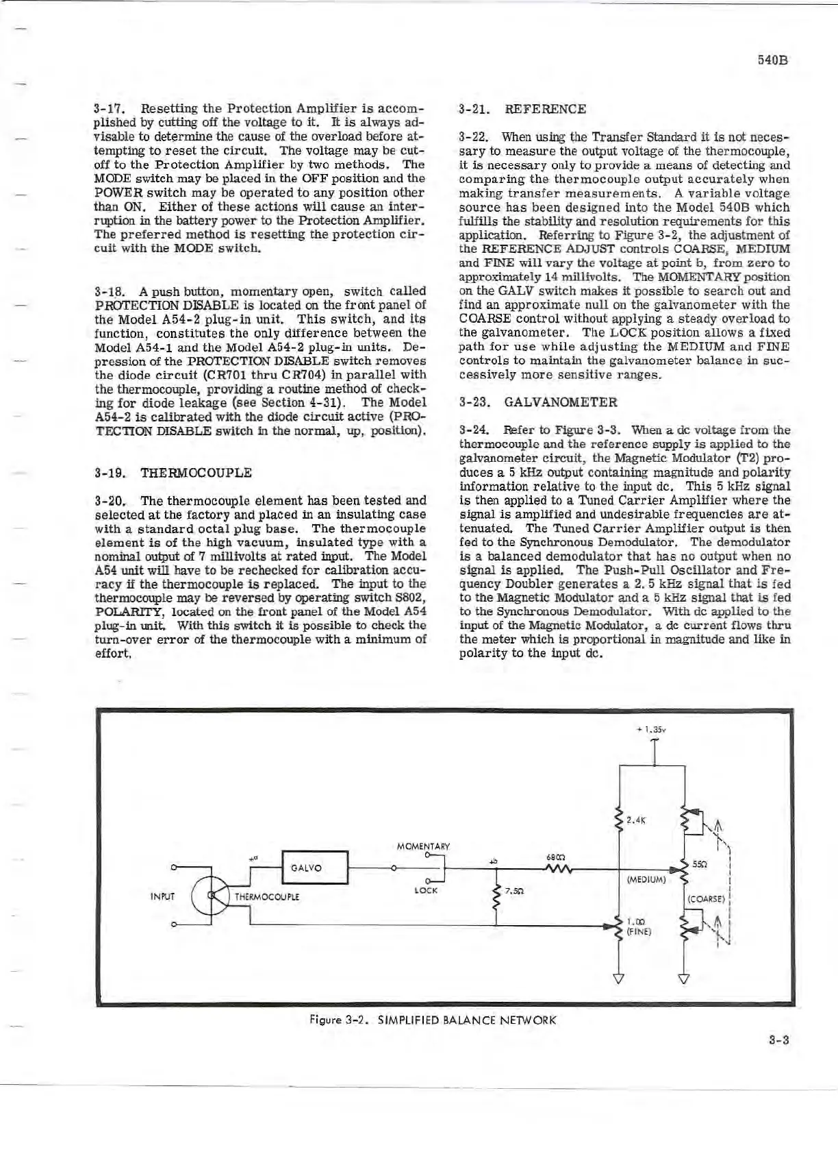
3-21.
REFERENCE
3-22.
When
using the
Transfer
Standard
it
is
not
neces-
sary
to
measure
th
e output voltage of the thermocouple,
it
is
necessary
only to provide a means of detecting and
comparing
the
thermocouple
output
accurately
when
making
transfer
measurements.
A
variable
voltage
source
has
been
designed
into
the
Model
540B
which
fulfills
the
stability and resolution
requirements
for
this
application. Referring to Figure
3-2,
the adjustment of
the
REFERENCE ADJUST
controls
COARSE, MEDIUM
and FINE will
vary
the
voltage
at
point b,
from
zero
to
approximately 14 millivolts. The
MOMENTARY
position
on the
GALV
switch makes
it
possible
to
search
out and
find an
approxim
ate
null
on
the
galvanometer
with
the
COARSE
control
without applying a
steady
overload
to
the
galvanometer.
The
LOCK
position
allows
a fixed
path
for
use
while
adjusting
the
MEDIUM
and
FINE
controls
to
maintain
the
galvanom
eter
balance
in
suc-
cessively
more
sensitive
ranges.
3-23.
GALVANOMETER
3- 24. Refer
to
Figure 3-3. When a de voltage
from
the
thermocouple and
the
reference
supply
is
applied
to
the
galvanometer
circuit,
the Magnetic Modulator (T2)
pro-
duces a 5 kHz output containing magnitude and
polarity
information
relative
to
the
input de.
This
5 kHz
signal
is
then applied
to
a ·Tuned
Carrier
Amplifier
where
the
signal
is
amplified and
undesirable
frequenci
es
are
at-
tenuated.
The
Tuned
Carrier
Amplifier
output
is
then
fed
to
the
Synchrono
us
Demodulator. The demodulator
is
a
balanced
demodulator
that
has
no
output
when no
signal
is
applied.
The
Push-Pull
Oscillator
and
Fre
-
quency
Doubler
generates
a 2.
5kHz
signal
that
is
fed
to
the
Magnetic Modulator and a 5 kHz
signal
that
is
fed
to
the Synchronous Demodulator. With de applied
to
the
input of
the
Magnetic Modulator, a de
current
flows
thru
the
meter
which
is
proportional in magnitude and like in
polarity
to
the
input de.
-+
1.l5
v
2.4K
680Ω
{MEDIUM)
7.5Ω
{FINE)
Figure
3-2.
SIMPLIFIED BALANCE NETWORK
3-3