Do you have a question about the Fluke 540B and is the answer not in the manual?
Detailed parameters including voltage ranges, accuracy, and calibration.
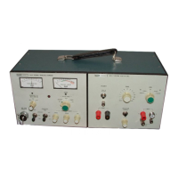
Description of the external controls, terminals, and indicators.
Important safety and operational advice to prevent damage or ensure accuracy.
Procedure for checking battery charge levels.
Procedures for measuring and calibrating AC and DC voltages.
Procedures for measuring and calibrating AC and DC currents.
Procedures for measuring and calibrating high-frequency voltages.
Detailed breakdown of key circuits like Search, Protection, and Thermocouple.
Explanation of the protection circuit and its operation.
Procedure for installing and removing batteries.
Recommended annual maintenance procedures.
Procedure to check transfer ranges without full calibration.
Common problems and their solutions.
Detailed diagrams showing the instrument's electrical circuits.
| Resolution (°C) | 0.1 °C |
|---|---|
| Resolution (°F) | 0.1 °F |
| Display Type | LCD |
| Input Voltage Range | Not applicable |
| Frequency Range | Not applicable |
| Accuracy (Voltage) | Not applicable |
| Temperature Range (°C) | 1372 °C |
| Temperature Range (°F) | -418 °F to 2501 °F (Type K) |
| Thermocouple Compatibility | J, K, T, E |
| Operating Temperature | 0 °C to 50 °C |
| Humidity Range | 90 % RH (non-condensing) |
| Storage Temperature | -20 °C to 60 °C |