540B
SECTION I
INTRODUCTION
AND
SPECIFICATIONS
1-1.
INTRODUCTION
1-2.
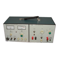
The Model 540B,
together
with
the
Model A54-1
or
Model A54-2 Voltage
Plug-In
Units,
constitutes
an
AC-DC
Thermal
Transfer
Standard.
The
unit
has
14
ranges
of
input
from
0.
5
volts
to
1,
000
volts.
It
is
furnished
complete
with
a
solid-state
galvanometer,
internal
reference,
search
meter
and
battery
power
supply.
A
voltage
protection
circuit
protects
all
in-
ternal
circuits
from damage
as
a
result
of over-voltages
of
up
to
1,
500
volts
on any range. Since
the
instrument
does not
require
critical
positioning
or
environment,
it
is
suitable
for
application
as
a
Laboratory
Standard,
yet
hardy
enough
for
use
as
a
production
line
or
field
instrument.
1-3.
The
solid-state
galvanometer
does
not
require
special
mechanical orientation
for
proper
operation and
is
no
more
fragile
than
any
normal
meter
movement.
The
circuit
is
equipped with an
internal
calibration
cir-
cuit
that
provides
easy
and
rapid
calibration
of
meter
deflection sensitivity representing 0.
1%
and .
01%
at
any
input.
1-4.
The
internal
reference
is
adjusted
by
Coarse,
Medium
and
Fine
controls
that
provide
continuous
ad-
justment
over
the
entire
range
of input
levels.
Good
resolution
is
possible
at
levels
below
50%
of
rated
in-
put,
but
sensitivity
is
sacrificed
with
the
lower
levels
of
input.
1-5
. A
search
meter
function has been included which
makes
the
selection
of
the
operating
range
certain
and
rapid.
1-6.
The self-contained
battery
pack
will
operate
the
instrument
independent
of
power
sources.
1-7.
SPECIFICATIONS
1-8.
ELECTRICAL
VOLTAGE RANGES
0.
5, 1, 2, 3, 5, 10, 20, 30, 50, 100, 200, 300, 500 and
1000 volts.
Transfers
may be made
on
each
range
from
1/2
to
1
times
range
voltage.
Transfers
may
be made
at
levels
considerably below
the
1/2
of
range
level, but
at
the
sacrifice
of sensitivity.
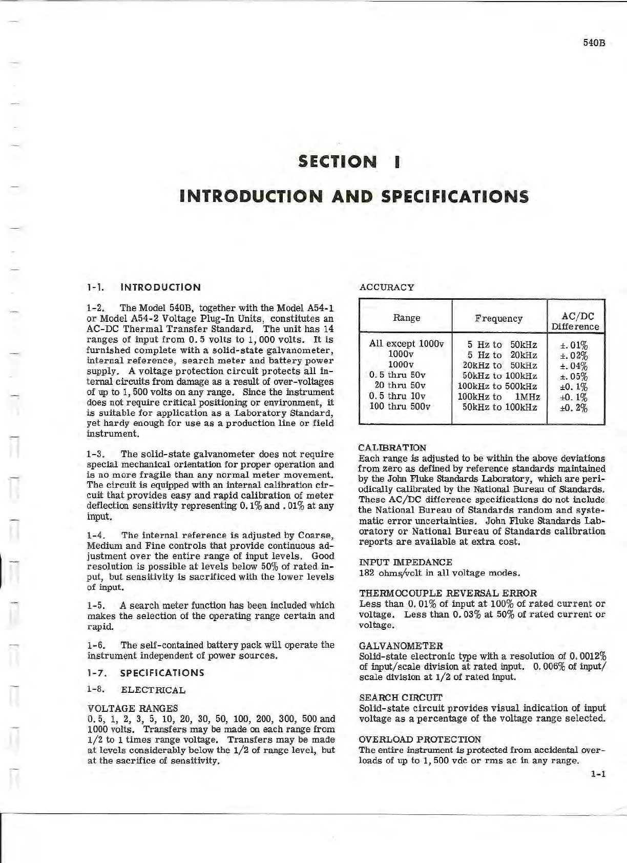
ACCURACY
Range
Frequency
AC/DC
Difference
All
except
1000v
5 Hz
to
50kHz
±.01%
1000v
5
Hz
to
20kHz
±.02%
1000v
20kHz
to
50kHz
±.04%
0. 5
thru
50v
50kHz
to
100kHz
±.05%
20
thru
50v
100kHz
to
500kHz
±0.1%
0.
5
thru
10v
100kHz
to
1M
Hz
±0.1%
100
thru
500v
50kHz
to
100kHz
±0.
2%
CALIBRATION
Each
range
is
adjusted
to be within
the
above deviations
from
zero
as
defined by
reference
standards
maintained
by the John Fluke Standards Laboratory, which
are
peri-
odically
calibrated
by the National
Bureau
of Standards.
These
AC/DC
difference
specifications
do not include
the
National
Bureau
of
Standards
random
and
syste-
matic
error
uncertainties.
John Fluke
Standards
Lab-
oratory
or
National
Bureau
of
Standards
calibration
reports
are
available
at
extra
cost.
INPUT IMPEDANCE
182 ohms/volt
in
all
voltage
modes.
THERMOCOUPLE REVERSAL ERROR
Less
than
0.
01%
of
input
at
100% of
rated
current
or
voltage.
Less
than
0.
03%
at
50%
of
rated
current
or
voltage.
GALVANOMETER
Solid-state
electronic
type with a
resolution
of
0.
0012%
of
input/scale
division
at
rated
input.
0.
006%
of
input/
scale
division
at
1/2
of
rated
input.
SEARCH CIRCUIT
Solid-
state
circuit
provides
visual
.
indication
of input
voltage
as
a
percentage
of
the
voltage
range
selected.
OVERLOAD PROTECTION
The
entire instrument
is
protected
from
accidental
over-
loads
of up
to
1, 500 vdc
or
rms
ac
in
any
range
.
1-1