54GB
6-6. SPECIFICATIONS
RANGE
0.
5, 1, 2,
3,
5, 10, 20, 30,
and
50
volts
NOI'E: Each
converter
may be used from
1/2
to
1
times
voltage
ra
ting.
AC/DC
DIFFERENCE 1
MHZ
10
MHZ
30
MHZ
50MHz
CONVERTER
0.5v
±0.
01%
+0.10%
+0.
60%
+1.
50%
1 - 10v ±0.
01%
±0.
03%
±0.
10%
±0.10%
20 - 50v
±0.
01%
±0.
05%
±0.10%
CALIBRATION
Calibration of the Model A55
is
referenced
to
the
center
oi
a
GR
874-TL
coaxial
tee
attached
to
the
converter
input connector. Each
range
is
adjusted
to
be within
the
above
deviations
from
zero
error
as
defined by
refer
-
ence
standards
maintained by the John Fluke
Standards
Laboratory
and
periodically
calibrated
by
the
National
Bureau
of
Standards.
These
ac/dc
difference
figures
do not include the National
Bureau
of Standards random
and
systematic
error
uncertainties. The 0. 5
volt
Model
A55
is
supplied
with a
test
report
indicating deviations
to
the
nearest
0.
01%
at
the
above
frequencies.
John
Fluke standards Laboratory
or
National Bureau of Stand-
ards
test
reports
are
available
at
extra
cost.
REVERSAL ERROR
Less
than
0. 025%.
INPUT IMPEDANCE
Approximately
200
ohms/volt.
OUTPUT VQLTAGE
7
millivolts
nominal
at
rated
input.
OUTPUT RESISTANCE
8
ohms
nominal.
INPUT
CONNECTOR
GR type
874-L
.
OUTPUT CONNECTOR
Amphenol 80- PC2M
2-pin,
micr
ophone type.
SIZE
AND
WEIGHT
Converter
Diameter
Length
Weight
0.5v
1-3/8"
3-
5/16"
10
oz.
1v, 2, 1-
3/8"
5-3/16"
13
oz.
3v
, 5,
1-
3/8"
6-
1/2"
15
oz.
10v, 20v 1-
3/8"
7-1/16"
1 lb.
30v, 50v
1-
3/8"
7-1/16"
1 lb.
6-7.
ACCESSORIES
6- 8. Model A55-110
Accessory
Kit
is
recommended
for
use
with Model
A55
Thermal
Converters
in
virtually
any calibration
or
measurement
setup. The
kit
includes:
a.
Coaxial
tee
for
Model
A55
input (GR type 874-TL).
6-2
b.
Three
coaxia
l
adapters
for
Model A55
input
(GR
type 874 to UHF, BNC,
and
type N
jacks).
c.
Interconnecting coaxial
cable,
ac
source
to
coaxial
tee.
d.
To
store
t
he
Model A55
Thermal
converters
and
accessories
, a Model C55
case
with a molded high
impact
styre
ne
insert
is
available (see
Figure
6-1).
The Model
C55
is
designed
to
accommodiate a
com
-
plete
set
of nine co
nverters.
6 - 9 . M ODEL
A40
AND
A40A
CU
RRE
NT
SHUN
TS
6- 10. INTRODUCTION
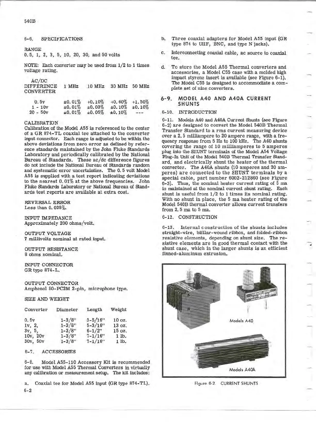
6- 11. Models A40 and
A40A
Current
Shunts (see Figure
6-
2)
are
designed
to
convert
the
Model 540B
Thermal
Transfer
Standard
to
a
rms
current
measuring
device
over
a 2. 5
milliampere
to
20
ampere
range, with a
fre-
quency
response
from
5Hz
to
100kHz. The A40 shunts
covering
the
range
of
10
milliamperes
to
5
amperes
plug into
the
SHUNT
terminals
of
the
Model A54 Voltage
Plug-In Unit of
the
Model 540B
Thermal
Transfer
stand-
ard,
and
electrically
shunt
the
heater
of
the
thermal
converter.
The A40A
shunts
(10
amperes
and
20
am
-
peres)
are
connected
to
the
SHUNT
terminals
by a
special
cable,
part
number
6002- 212860
(~ee
Figure
6-3).
Thus,
the
nominal
heater
current
ratmg
of 5
ma
is
maintained
at
the nominal
current
shunt
rating.
Each
shunt
is
useful
from
1/2
to
1
times
its
nominal
rating.
With no
shunt
in
pl
ace,
the
5 rna
heater
rating
of
the
Model 540B
thermal
converter
allows
current
transfers
from
2. 5 rna
to
5
ma
.
6-12.
CONSTRUCTION
6-13.
Internal
cons
t
ruction
of
the
shunts
includes
straight-wire,
bifilar-wound ribbon, and folded- ribbon
resistive
elements,
depending on
shunt
size.
The
re-
sistive
elements
are
in
good
thermal
contact
with
the
shunt
case,
which
in
the
larger
shunts
is
an
efficient
finned-aluminum
extrusion
.
Models A40
Models A40A
Figure 6-2.
CURRENT
SHUNTS