Theory of Operation
Introduction
2
2-3
2-1. Introduction
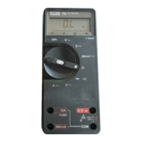
This chapter contains a brief overview of the 77 Series III Multimeter,
followed by a more detailed explanation of operation.
2-2. Functional Block Description
The heart of the instrument consists of a two-chip CMOS system: U1, a
primarily analog IC, and U2, a calculator-style microcomputer (see Figure 2-
1).
OHMS
300 mV
DCV
ACV
OFF
ACmV
DCmV
A/D
J1
Input
Signal
Conditioning
Range and
Function
Control
To Bar
Graph
To Digital
Display
LCD
S1
U2 Microcomputer
A/D Samples
Y1
32.768
kHz
Counter
U1 Analog Chip
V
REF
aaa01f.eps
Figure 2-1. Overview
2-3. Detailed Description
The following paragraphs describe the 77 Series III Multimeter in more detail.
While reading this description, refer to the schematic diagram in Chapter 5.
2-4. Voltage Signal Conditioning
Input divider Z1 and dc blocking capacitor C1 make up an input voltage signal
conditioning circuit.
 Loading...