77 Series III
Service Manual
2-6
Conditioned input signals are routed to the a/d converter in U1, where they are
integrated. The reference voltage developed by reference supply VR1, R15,
R16, and R8 is routed to the a/d converter in U1, where it is used for the
integrate reference (de-integrate) portions of the measurement cycle.
C7 stores offsets of the buffer, integrator, and comparator amplifiers of the a/d
converter. The gain of the buffer is determined by the resistors of Z1 between
pins 8, 9, and 10. C8 is the integrator capacitor.
A series of 10 minor cycle conversions occurs without taking time for an
autozero phase between the conversions. These minor cycle conversions, or
samples, occur at a rate of 25 per second, and are used to provide the fast
response bar-graph display and fast autoranging.
New samples are taken every 40 ms. Ten samples are summed to produce a
full- resolution digital display, with full scale greater than 3200 counts. A 50-
ms autozero phase occurs following every 10 sample sequence.
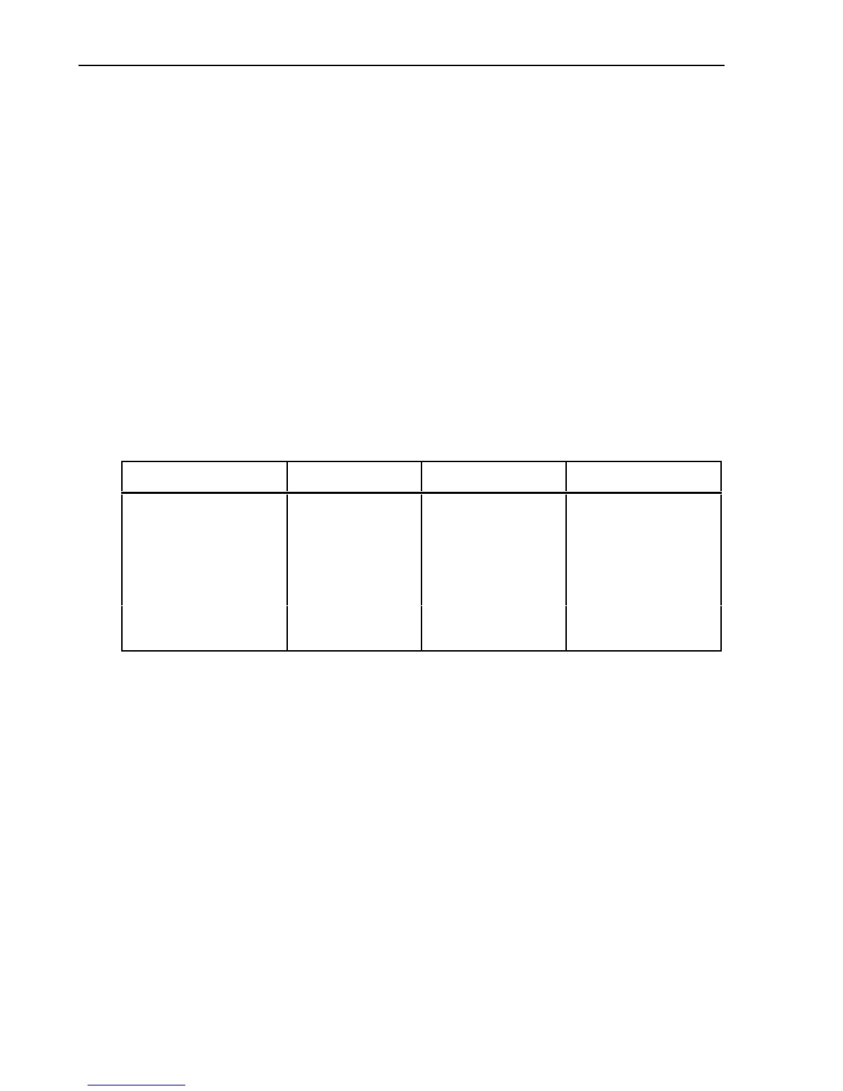
Table 2-1. S1 Function Codes
Function B0 B1 B2
ACV 1 1 1
DCV 0 1 1
300 mV 0 0 0
Ohms 0 0 1
10 0
ACA 1 1 0
DCA 0 1 0
 Loading...