77 Series III
Service Manual
1-4
1-3. Conventions
Through the manual, certain notational conventions are used. A summary of
these conventions follow:
• Instrument Reference
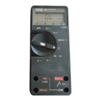
The Fluke 77 Series III Multimeter is also referred to throughout this
manual as “the meter”.
• Printed Circuit Assembly
The term “pca” is used to represent a printed wiring board and its
attached parts.
• Circuit Nodes
Individual pins or connections on a component are specified by a dash
(-) following the component reference designator. For example, pin 19
of U30 would be U30-19.
• User Notation
Generally, push buttons, function positions, input terminals, and
display notation are presented in this manual as they are seen on the
meter.
Special terms (mnemonics) used in text descriptions of meter circuitry
correspond to terms used on the schematic diagrams in Chapter 5.
1-4. Specifications
Specifications for the meters are presented in Table 1-1.
 Loading...