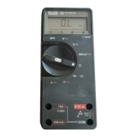
77 Series III
Service Manual
3-8
Table 3-2. DC Voltage Test
Step DC Input Voltage Display Reading
1 +2.7V 2.691 to 2.709V DC
2 +27V 26.91 to 27.09V DC
3 +270V 269.1 to 270.9V DC
4 +1000V 995 to 1005V DC
5* +300 mV 299.0 to 301.0V DC
*300 mV function only
3-8. AC Voltage Test
Warning
Connect the ground/common/low side of the AC
calibrator to COM on the UUT.
1. Set the UUT function switch to VAC, and connect the AC Voltage
Calibrator to the z and COM input terminals.
2. Set the AC Voltage Calibrator for the output given in Table 3-3,
verify that the UUT display reading is within the limits shown.
Note
When the input is open in the VAC function, it is normal for
the meter to read some counts on the display. This is due to
ac pickup in the ac amplifier when the ac amplifier when the
ac amplifier is unterminated.
Table 3-3. AC Voltage Test
Input
Step Voltage Frequency Display Reading
1 2.7V 100 Hz 2.644 to 2.756V AC
2 2.7V 500 Hz 2.644 to 2.756V AC
3 1000V 100 Hz 978 to 1022V AC
4 1000V 1000 Hz 978 to 1022V AC
3-9. Resistance Test
1. Select the ohms function on the UUT.
2. Connect the Ohms Calibrator or Decade Resistor to the z and
COM input terminals of the UUT.
 Loading...